
CHAPTER 9 - RAY OPTICS AND OPTICAL INSTRUMENTS
Spherical Mirrors
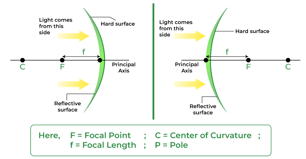
Spherical mirrors are generally constructed from glass. A spherical surface is a part cut from a hollow sphere. This curved surface of the glass has a silver coating on one side and a polished surface on the other, where the reflection of light takes place. The term “convex mirror” refers to a mirror where the reflection occurs at the convex surface, and the term “concave mirror” refers to a mirror where the reflection occurs at the concave surface. The passenger-side wing mirrors of automobiles are the most common examples of convex mirrors.
Table of Content
Spherical Mirrors
A spherical mirror or a mirror that is a part of a sphere is a mirror that has the shape of a piece that is cut out of a spherical surface or material. There exist two types of spherical mirrors which are: Concave and Convex mirrors.
Spherical Mirror Formula
The spherical mirror formula is a relation that describes how object distance (u) and image distance (v) are related to the focal length (f) of a spherical mirror. The spherical mirror equation is one of the most important relations from optics in Physics.
The spherical mirror formula is given as,
1/f = 1/v + 1/u
Here,
- f is the focal length
- v is the image distance
- u is the object distance
The focal length of the mirror is equal to half of the radius of curvature of the spherical mirror and is given by the relation:
f = R/2
where,
- f is the focal length of the spherical mirror
- R is the Radius of Curvature of the spherical mirror
Magnification of the spherical mirror, determines how smaller or bigger the image is formed after reflection from the spherical mirror. Magnification is given either by the ratio of image and object height or by the ratio of image and object distance of the mirror.
m = I/O = v/u
where,
- I is the Height of the Image formed
- O is the Height of the Object
- v is the image distance
- u is the object distance
History of Spherical Mirrors in Human Civilization
As early as 30,000 years ago, people used spherical mirrors to collect water in prehistoric containers or reflect items in quiet, dark water (or utensils).
The first mirrors were made from polished volcanic glass, such as obsidian, and are the oldest examples of produced mirrors.
Mirrors made of obsidian that date to roughly 6000 BC have been discovered in Anatolia (now Turkey). Around 3000 BC and 4000 BC, respectively, polished copper mirrors were created in Mesopotamia and ancient Egypt.
Spherical mirrors have been utilized by human civilization for a very long time, not just in those areas.
Polished stone mirrors from the year 2000 BC have also been found in Central and South America. Since 2000 BC, China has been making bronze mirrors.
Basic Terminologies for Spherical Mirrors
There are some common terms that we need to know while studying spherical mirrors, and they are as follows:
- Centre of Curvature: The point in the centre of the mirror surface that passes through the curve of the mirror and has the same tangent and curvature at that point. It is represented by the capital letter C.
- Radius of Curvature: It is considered the linear distance between the pole and the centre of curvature. It is represented by the capital letter R, R=2f
- Principal axis: An imaginary line that passes through the optical centre and from the centre of curvature of a spherical mirror. All the measurements are based on this line.
- Pole: The midpoint or the centre point of the spherical mirror. It is represented by capital P. All the measurements are made from it only.
- Aperture: An aperture of a mirror is a point from which the reflection of light actually takes place or happens. It also gives an idea about the size of the mirror.
- Principal Focus: Principal Focus can be called the Focal Point also. It is present on the axis of a mirror where the rays of light parallel to the principal axis converge or appear to converge or diverge after reflection.
- Focus: It is any given point on the principal axis where light rays parallel to the principal axis will converge or appear to converge after getting reflected from the mirror.
Structure of Spherical Mirrors
A spherical mirror can be a concave or a convex mirror depending upon the surface of the reflection. If it is bulged out then it is a convex spherical mirror whereas if it is bent inwards it is termed as a concave spherical mirror.
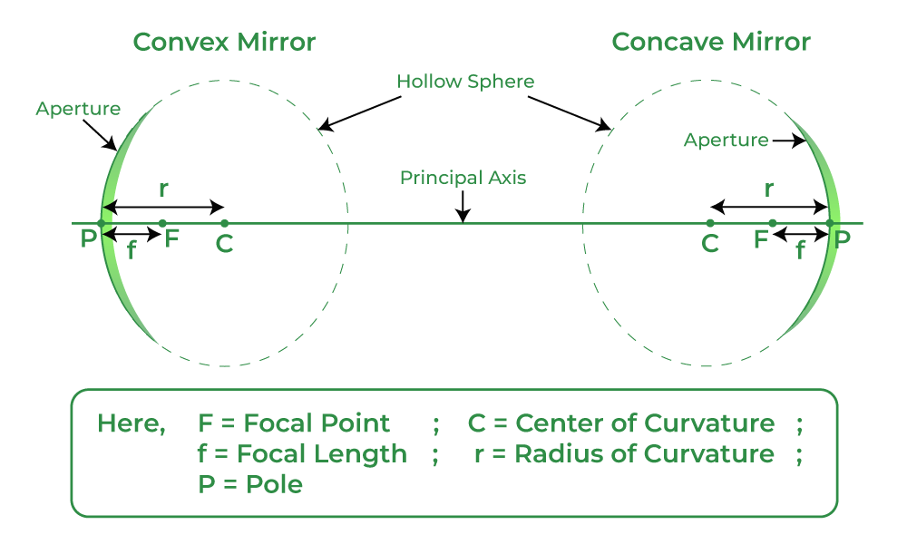
A typical spherical mirror is a part of a big sphere of which the cut-out has been taken. The following diagram describes different parts which are there in a spherical mirror. The definition of these parts is already given above.
Types of Spherical Mirrors
Spherical Mirrors are of two types, namely:
- Concave Mirrors
- Convex Mirrors
The two types of spherical mirrors are discussed in detail:
Concave Mirror
A spherical mirror of which the reflecting surface is curved inwards which means that it faces towards the centre of the sphere is known to be a concave mirror. The back of the mirrors is always shaded so that reflection can take place only from the inward bulged surface.
The surface of the spoon which is curved inwards can be approximated to a concave mirror. It is also known as the converging mirror as the ray of light after bouncing back from it appears to converge at some points where we can obtain a real, inverted, and enlarged or diminished image based on the location of the object.
Uses of Concave Mirror
- Converging mirrors are most widely used in shaving because they have reflective and curved surfaces.
- A concave mirror is used in the ophthalmoscope
- These mirrors are also widely used in making astronomical telescopes. In an astronomical telescope, a converging mirror of a diameter of about 5 meters or more is used as the objective.
- Converging mirrors are widely used in headlights of automobiles and in motor vehicles, torchlights, railway engines, etc. as reflectors.
- Large converging mirrors are used to focus the sunlight to produce heat in the solar furnace.
Convex Mirror
A spherical mirror having its reflecting surface curved outwards is known to be a convex mirror. The back of the mirror is shaded so that reflection only takes place from the outward bulged part. The surface of the spoon which is bulged outwards can be assumed to be a convex mirror. It is also known as a diverging mirror as the light after reflecting through its surface diverges to many directions but appears to meet at some points where the virtual, erect image of diminished size is formed.
Uses of Convex Mirror
- Convex mirrors are used inside buildings so that people can see all around the building at once.
- The convex mirror is used in vehicles. Convex mirrors are commonly used as rear-view mirrors in the case of automobiles and vehicles because they can diverge light beams and make virtual images.
- These mirrors are mostly used for constructing magnifying glasses. In industries, to construct a magnifying glass, two convex mirrors are placed back to back.
- Diverging mirrors are also used for security purposes in many places. They are placed near ATMs to let the bank customers check whether someone is behind them or not.
- Convex mirrors are also widely used in various other places for example streetlight reflectors because they can spread light over bigger areas.
Sign Conventions for Spherical Mirrors
A set of rules that are used to set signs for terms like the object distance, image distance, focal length, etc used in spherical mirrors for mathematical analysis during the image formation are called the Sign Conventions for Spherical Mirrors.
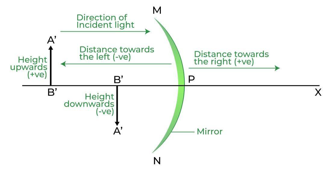
According to the sign convention for spherical mirrors:
- All distances are measured or taken from the pole of the spherical mirror.
- Objects are considered to be placed on the left side of the spherical mirror.
- The distances measured along the direction of the incident ray are taken as positive while, the distance measured along the direction of the reflected ray or opposite is taken as negative.
Image Formation by Spherical Mirrors
Image formed by any type of mirror can be found either where the reflected light appears to diverge from or where it converges. We have two types of spherical mirrors Concave and Convex Mirrors. Let’s discuss the image formation in each type of mirror as:
Images Formed by Concave Mirrors | |||
|---|---|---|---|
Position of Object | Ray Diagram | Position of Image | Nature of Image |
| At Infinity (∞) | 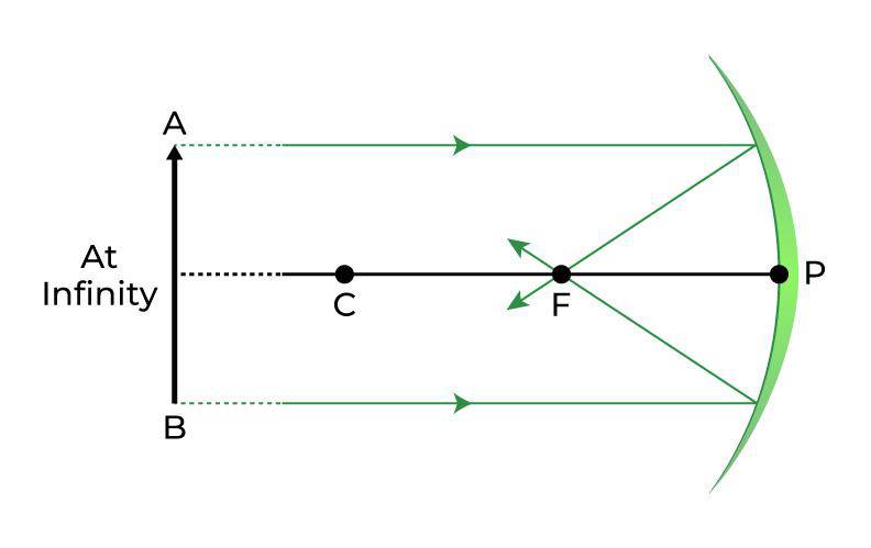 | At the Principal Focus (F) | Real, inverted and extremely smaller in Size |
| Beyond the Centre of Curvature (C) |  | Between principal Focus (F) and Center of Curvature (C) | Diminished, Real and Inverted |
| At the Centre of Curvature (C) | 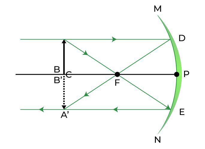 | At the Center of Curvature (C) | Same size as the object, Real and Inverted |
| Between Focus (F) and Center of Curvature (C) | 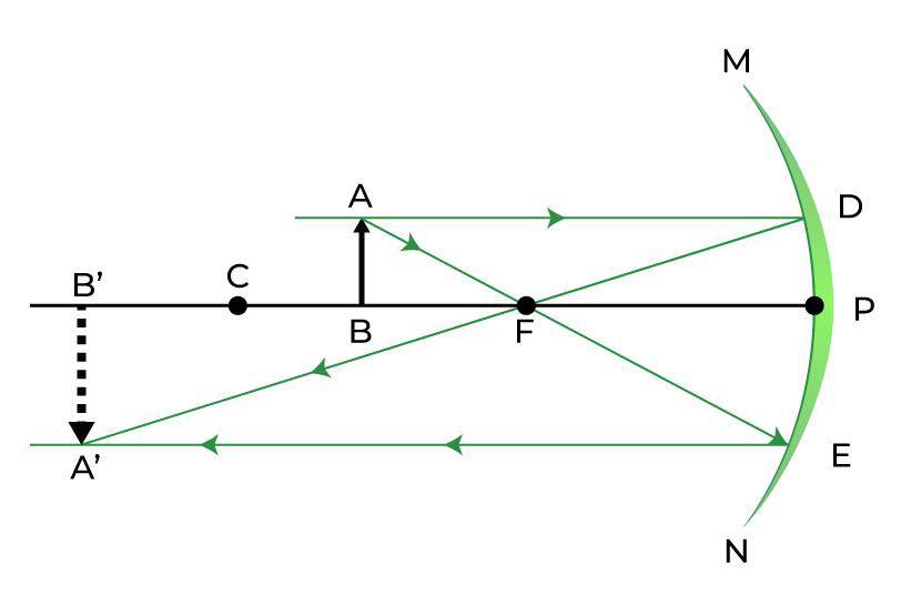 | Beyond Center of Curvature (C) | Magnified, Real, and Inverted |
| At the Principal Focus (F) | 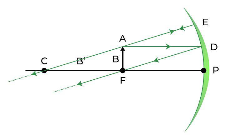 | At Infinity (∞) | Highly Magnified |
| Between the Pole (P) and Focus (F) |  | Behind the Mirror | Magnified, Virtual, and Erect |
Properties of the Image formed by Concave Mirrors
- Point-sized image, highly diminished in size, Real and inverted image.
- The parallel lines which come from the very distant object at infinity after striking the reflecting surface of the concave mirror get reflected back and meet at a point, or we can say in this case converge at a point. This point is known as the principal focus of the concave mirror.
Images Formed by Convex Mirrors | |||
|---|---|---|---|
Position of Object | Ray Diagram | Position of Image | Nature of Image |
At Infinity (∞) |  | Behind the mirror at Principal Focus (F) | Highly Diminished, Virtual, and Erect |
Between infinity and pole (P) of the mirror |  | Between Pole (P) and Focus (F), behind the mirror | Highly Diminished, Virtual, and Erect |
Properties of the Image formed by Convex Mirrors
- The image formed is highly diminished in size, virtual, and erect.
- The parallel lines which come from the very distant object at infinity after striking the reflecting surface of the convex mirror get reflected back and appear to meet at a point, or we can say in this case diverge from the surface and appear to meet at a point. This point is known as the principal focus of a convex mirror.
Check: Convex Mirror Image Formation: Conditions, and Ray Diagrams
Uses of Spherical Mirrors
- Concave mirrors are used torch headlights to disperse light over a larger surface, hence enhancing the field of vision.
- Convex mirrors are used in car’s rearview mirror, as it gives a wider field of view, that helps the driver to see most of the traffic behind him.

- Concave mirrors are used in solar cookers as reflectors to focus sunlight on a specific area and raise the box’s temperature.
- Convex mirrors are used in the rear-view mirror to provide a larger view of the road and oncoming traffic.
- Concave mirrors are used in telescopes, satellite dishes, and by dentists and ENT specialists to create images of the teeth, ears, skin, and other body parts that are larger than the actual.

Also Read,
- Image Formation by Spherical Mirror
- Sign Convention for Spherical Mirror
- Program to determine focal length of a spherical mirror
- Determine focal length of a spherical mirror
Spherical Mirrors – FAQs
What are Applications of Spherical Mirrors?
Daily Life Applications of Spherical Mirrors are,
- In Rear-view Mirrors of automobiles to see behind the car, etc.
- In security mirrors used in banks, ATMs, stores, etc.
- Satellites uses concave mirrors to receive and enhance signals.
- Concave mirrors are used in solar cookers as reflectors to focus sunlight on a specific area and raise the temperature of the box.
How Many Types of Spherical Mirrors are There?
There are two types of spherical mirrors, they are:
- Concave Mirror
- Convex Mirror
What is “Radius of Curvature” for spherical mirrors?
Radius of Curvature: is considered the linear distance between the pole and the centre of curvature. It is represented by the capital letter R. And it is related to focal length length f as, R = 2f
What is Principal Focus of a Concave Mirror?
When a parallel beams of light rays are incident on a concave mirror they after reflection through its surface converge at a particular point on the principal axis which is known as principal focus of concave mirror.
What is Principal focus of a Convex Mirror?
When a parallel beams of light rays are incident on a convex mirror they after reflection through its surface diverge through its surface but appear to meet at a particular point on the principal axis which is known as principal focus of convex mirror.
What is Pole in Spherical Mirrors?
The midpoint or the centre point of the spherical mirror. It is represented by capital P. All the measurements are made from it only.
Name the Mirror Used in Car’s Rear-view Mirror.
Convex mirrors are used in car mirrors.
Refraction of Light
Refraction is an important term used in the Ray Optics branch of Physics. Refraction of light is defined as the change in direction or the bending of a wave passing from one medium to another due to the change in speed of the wave. Some natural phenomena occurring in nature where refraction of light takes place are the twinkling of stars, the formation of mirages and Rainbows, Optical illusions, and many more. The major cause of refraction to occur is the change in the speed of waves in different mediums, which is different due to the difference between the densities of the mediums. e.g. the speed of light in a vacuum is maximum. Snell’s Law provides a quantitative description of the amount of bending of a wave, that depends on the refractive index of the two mediums. Let’s learn more about refraction like the Laws of Refractions, Causes of Refraction, Types of Refraction, Examples, and Applications of Refractions in the article below.
What is Refraction of Light?
The bending of a light wave when it passes from one medium to another due to the change in the speed of the light traveling the two different media is called the Refraction of light.
This phenomenon also occurs with sound, water, and other waves. Because of this bending of waves that are responsible for the refraction of light, we have lenses, magnifying glasses, prisms, and rainbows. Due to this phenomenon, our eyes would not be able to focus, without the refraction of light.
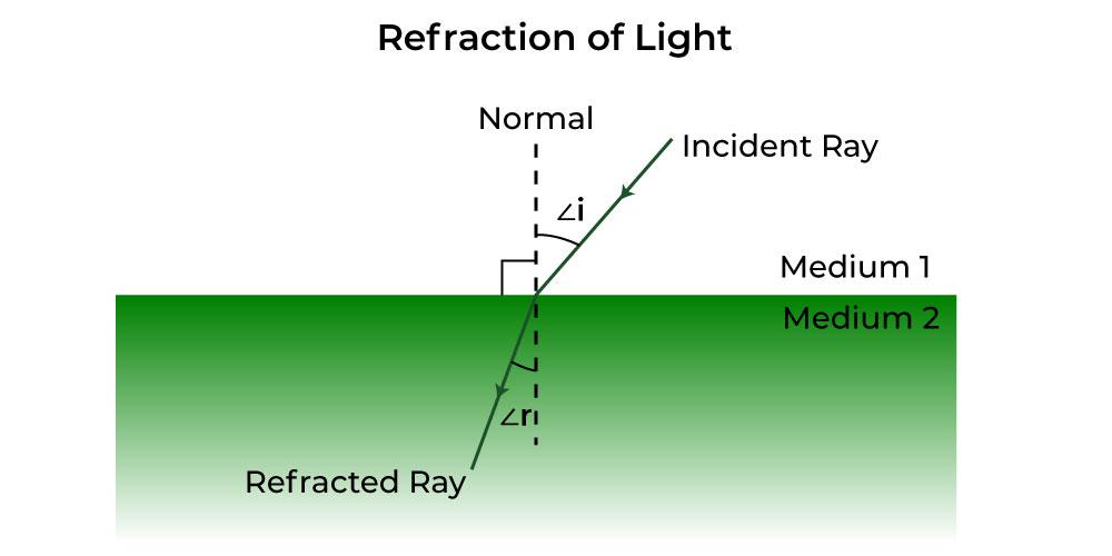
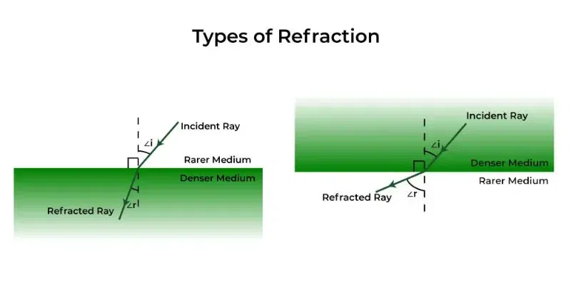
As shown in the above figure, light travels from Medium 1 to Medium 2. Please note that these mediums can be different materials or substances with different densities. So when an incident ray from medium 1 travels to another medium 2, the refracted ray bends either towards the normal or away from the normal (depending upon the densities of the mediums).
Here are the definitions of important terms used to study Refraction:
- Normal – The point of the surface at which an optical phenomenon occurs is called the normal. In simple words, it is termed the point of incidence. It is shown by a dotted line drawn perpendicular to the surface of the refracting material, in a ray diagram.
- Incident Ray – The light rays that strike the refracting surface, at the separation of two media are called the Incident Ray.
- Refracted Ray – The light rays that bend after passing into another medium are called the Refracted Ray.
- Angle of Incidence – This is the angle between the incident ray and the normal. It is represented by ∠i and it is also called an Incident angle.
- Angle of Refraction – This is the angle between refracted ray and the normal. It is represented by ∠r and it is also called a Refracted angle.
Laws of Refraction of Light
The refraction of light traveling through different mediums follows some laws. There are two laws of refraction as stated below which at the sight of refraction, the light follows, and we see the refracted image of the object.
- The reflected, incident, and the normal at the point of incidence all will tend to lie in the same plane.
- Secondly, the ratio of the sine of the angle of the incidence and refraction is constant which is termed Snell’s law.
sin i / sin r = Constant (n)
where i is the angle of incidence, r is the angle of refraction, the constant value depends on the refractive indexes of the two mediums.
What is the Refractive Index?
The Refractive index also called the index of refraction enables us to know how fast light travels through the material medium.
Refractive Index is a dimensionless quantity. For a given material or medium, the refractive index is considered the ratio between the speed of light in a vacuum (c) to the speed of light in the medium (v) on which it goes. The Refractive index for a medium is represented by small n, and it is given by the following formula:
n = c / v
where
- c is the speed of the light in a vacuum, and
- v is the speed of light in the medium.
The given velocities of light in different media can give the refractive index by the following also where the first medium is not vacuum:
n21 = v1 / v2
where n21 is the refractive index of 2 with respect to 1.
Based on the given refractive index of the material or medium, the light ray either changes its direction or bends at the junction which separates the two given media. If the light ray travels from a certain medium to another of a slightly higher refractive index, it bends towards the normal in that case when traveling from rarer to a denser medium, or else it bends away from the normal when traveling from denser to rarer medium.
Snell’s Law
Snell’s law provides the degree or extent of refraction that occurs through a relationship between the incident angle, refracted angles, and the refractive indices of a given pair of media.
According to Snell’s law, the ratio of the sine of the incident angle to the sine of the refracted angle is a constant, for any light of a given color or for any given pair of media. The constant value is called the refractive index of the second medium with respect to the first.
Snell’s Law is given by the relation,
or
where,
- i and r are the angle of incidence and refraction,
- n is the refractive index and n1 and n2 are the refractive indices of medium 1 and 2, and
- v1 and v2 are the speed of light in medium 1 and 2 respectively.
Causes of Refraction of Light
As it is known that when light travels in different mediums its speed varies. e.g. light passes through the air than in a glass. Hence, it can be said that, due to the change in the speed of light in different mediums that the light rays are refracted.
To understand the causes of refraction of light in much depth let’s understand What are rarer and denser mediums? and Types of Refractions as:
What are Rarer and Denser mediums?
- Rarer medium (or Optically Rarer medium) is a medium in which the speed of light is more. For example, Air is optically rarer medium as compared to glass and water.
- Denser medium (or Optically Denser medium) is a medium in which the speed of light is less. For example, Glass is optically denser medium as compared to air.
Types of Refraction
The refraction of light occurs in different ways depending on the medium through which the light travels.
- Refraction from denser to rarer medium – When light rays pass through rarer to a denser medium, the light rays bend towards the normal. Due to this the angle of refraction is smaller than the angle of incidence. e.g. In the case when light rays pass from air to water or from air to glass, it bends towards normal. It is because of the reason that the speed of light rays reduces while passing from air to glass or water.
- Refraction from rarer to denser medium – When light rays pass from denser to rarer medium, the light rays bend away from the normal. Due to this the angle of refraction becomes more than the angle of incidence. e.g. In case when light rays pass from water to air or glass to air, light rays bend away from the normal. The speed of light rays becomes greater while passing from glass or water to air.
Characteristics of Refraction
Some of the important characteristics of Refraction are:
- The frequency of light does not change when it travels from one medium to another, but the velocity and wavelength of light changes.
- A ray of light bends when it travels from one optical medium to another with a variable refractive index. For a specific pair of media, the ratio of the sine of the angle of incidence to the sine of the angle of refraction is constant.
- The relationship between a medium’s refractive index and the speed of light in that medium is as follows:
where,
- i and r are the angle of incidence and refraction,
- n is the refractive index and n1 and n2 are the refractive indices of medium 1 and 2, and
- v1 and v2 are the speed of light in medium 1 and 2 respectively.
Effects of Refraction of Light
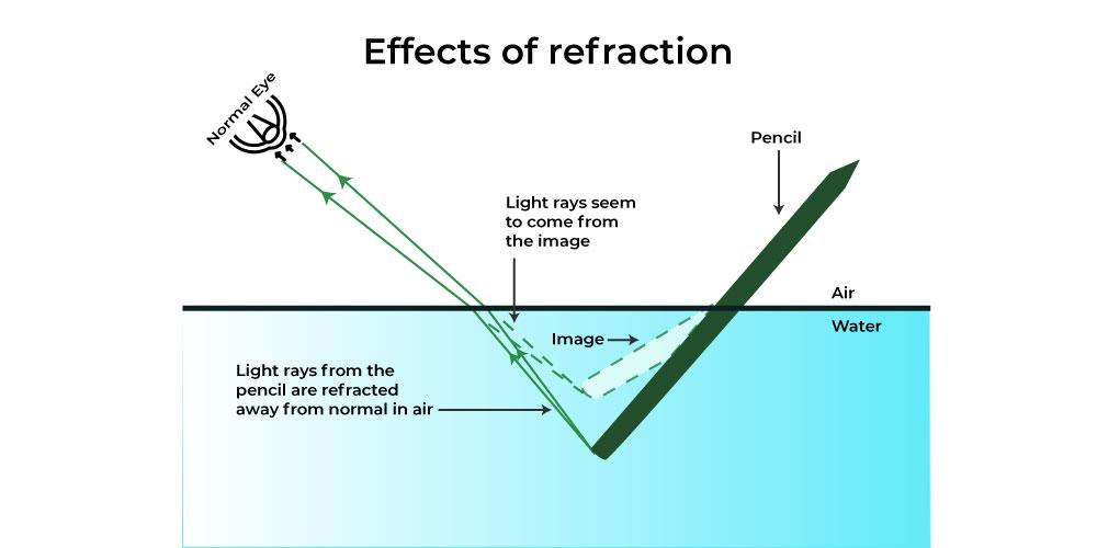
When anything interrupts the light waves, it causes refraction of the light. Light also moves mostly in the form of waves, much like most other materials.
As shown below, the pencil seems deformed in the water because light cannot travel through the water as rapidly as it can through the air. The pencil has a tiny magnification effect due to the light refraction, which makes the angle appear larger than it actually is and makes the pencil appear crooked.
Examples of Refraction of Light
- The stars twinkle in the night sky due to the refraction of their light.
- Looming and Mirage formation, both occur due to the optical illusions caused by the refraction of light.
- The formation of rainbows in the sky and VIBGYOR, when white light passes through the prism are also major examples of refraction.
- A swimming pool always seems or looks much shallower than it really is because of the light that comes from the bottom of the pool bends at the surfaces due to the refraction of light.
Applications of Refraction of Light
Refraction has many wide and common applications in optics and also in technology. A few of them are given below:
- A lens uses the refraction phenomenon to form an image of an object or body for various purposes, such as magnification.
- Spectacles that are worn by people with defective vision use the principle of refraction.
- Refraction is used in peepholes of the house doors for safety, in cameras, inside movie projectors, and also in telescopes.
Read More,
Solved Examples on Refraction of Light
Example 1: What is the constant value if the angle of incidence is 22° and the angle of refraction is given to be 15°?
Solution:
As we know,
sin i / sin r = constant
Given sin i = sin 22° and sin r = sin 22°
Putting the values of angles from log table we get
sin 22° / sin 15° = 1.44
Hence, the value of constant or refractive index is 1.44.
Example 2: What is the constant value if the angle of incidence is 30° and the angle of refraction is given to be 46°?
Solution:
Since, the
sin i / sin r = constant
Given sin i= sin 30° and sin r= sin 46°
Putting the values of angles from log table we get
sin 30° / sin 46° = 1.44
Hence, the constant is 1.44.
Example 3: What is the value of the sine of the angle of incidence if the angle of refraction is given to be sin 35°? Given the value of refractive index 1.33.
Solution:
As we know,
{sin i}/{sin r} =constant
Given constant= 1.33 and sin r = sin 35° = 0.57
Putting the values of angles from log table we get
sin i / sin 35° = 1.33
sin i = 1.33 × 0.57
= 0.75
Example 4: Calculate the speed of light in diamond with respect to air. Take the absolute refractive index of glass from the table.
Solution:
As we know we can calculate refractive index by the following formula,
n = c/v
where refractive index of diamond n= 2.42, c = 3 × 10⁸ m/s
Hence, the velocity or speed of light in glass is vd = 1.24 × 10⁸ m/s
FAQs based on Refraction of light
Define the term Refraction.
The change that occurs in the direction of a wave when light passes from one medium to the other is known as refraction of light.
When is the refraction of light not possible?
When the light is incident perpendicular to the boundary or surface, refraction of light is not possible.
What is the difference between reflection and refraction in light?
The bouncing back of light when it strikes a smooth surface is called Reflection. While the bending of a light ray when it travels from one medium to other is called refraction of light.
Give an example of the Refraction of light.
There are many examples of refraction of light observed in our daily life like the Twinkling of stars. The Twinkling of stars is because of the atmospheric refraction occurs by the light from the star undergoing a gradual change in the medium.
Total Internal Reflection
In Physics, total internal reflection is the complete reflection of a light ray within the medium (air, water glass, etc). For example, the total internal reflection of rays of light takes place in a Diamond. Since Dimond has multiple reflecting surfaces through which the Total internal reflection takes place. The total internal reflection occurs when light travels from a denser medium to a less dense medium and the angle of incidence must be greater than the critical angle. The phenomenon of total internal reflection has a wide application in optical devices such as telescopes, binoculars, periscopes, etc. Read more about the concepts of Total Internal Reflection like Total Internal Reflection of Light, definition, critical angle, and total internal reflection, examples, and FAQs, here in this article!
What is Total Internal Reflection?
The complete reflection of a light ray at the boundary of two media when the beam is in the medium with a higher refractive index is known as total internal reflection.
This is due to the fact that when there is water in the glass, light from the coin travels through the glass at a certain angle to our sight. Further, when water is added to the glass, the light from the coil strikes the interior of the glass at a higher angle than the critical angle. The glass inside reflects 100% of the light. Internal reflection is what it is.
Conditions for Total Internal Reflection
When light beams go from a more optically dense material to a less optically dense medium, this phenomenon happens. There are two situations in which total internal reflection occurs:
- When the light is approaching the less dense medium from the more dense medium.
- If the incidence angle is larger than the critical angle.
Total Internal Reflection Formula
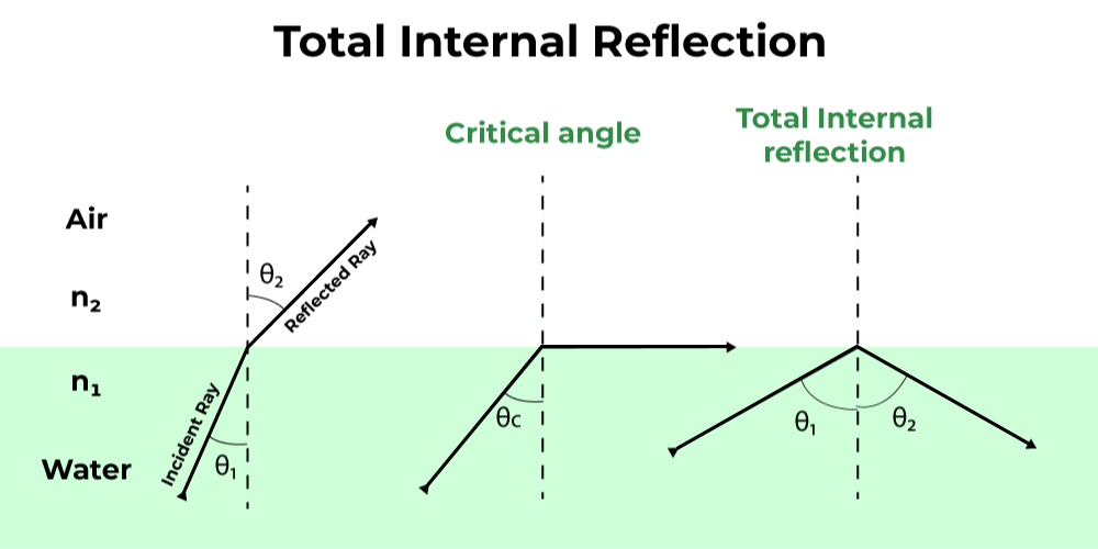
Consider the case below. A beam of light travels from a watery medium to one of air. The light ray will be refracted at the point where the two mediums meet. The refracted light beam bends away from the normal as it passes from a medium with a higher refractive index to one with a lower refractive index.
- The incident beam of light is refracted in such a way that it travels over the water’s surface at a certain angle of incidence.
- The critical angle is the angle of incidence at which something happens. The refraction angle is 90° here.
- The incident ray is reflected back to the medium when the angle of incidence is larger than the critical angle. This event is referred to as total internal reflection.
The formula for total internal reflection is stated as:
n1 ⁄ n2 = sin θ1 ⁄ sin θ2
where,
- θ1 is the angle of incidence,
- θ2 is the angle of refraction,
- n1 is the denser medium, &
- n2 is the rarer medium.
Critical Angle
Critical angle is defined as the largest angle of incidence for which refraction of light inside the medium still can be possible. Therefore, the angle of incidence, when the angle of refraction is 90 degrees and the ray which is refracting to total internal refraction is called the critical angle.
Mathematically, the critical angle for a total internal reflection is defined as,
θc = sin−1(n2 ⁄ n1)
where,
- θc is the critical angle.
- n1 is the denser medium, &
- n2 is the rarer medium.
Total Internal Reflection Examples
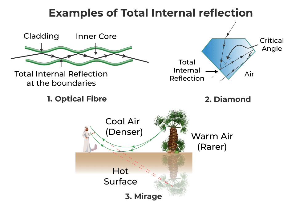
Total Internal Reflection in Optical Fiber
Because the angle generated by the incoming beam is higher than the critical angle, total internal reflection occurs when it strikes the cladding. Optical fibers have revolutionized the speed with which signals are carried across cities, nations, and continents, making telecommunication one of the quickest forms of information transportation. Endoscopy also uses optical fibers.
Total Internal Reflection in Mirage
It’s an optical illusion that causes the water layer to appear at short distances in the desert or on the road. Total internal reflection, which happens as a result of atmospheric refraction, is an example of a mirage.
Total Internal Reflection in Diamond
When light rays penetrate a diamond, they are completely internalized and reflected on all of the diamond’s facets. The crucial angle for a beam of light going from a diamond to air is just 24°. As a result, the majority of incoming photons experience complete internal reflections.
Furthermore, diamonds are often cut in such a way that when a beam of light penetrates them, it is subjected to entire internal reflections on multiple faces. When the angle of incidence at any face is less than 24°, light shines through, making the diamond look brilliant. Optical fibers also employ total internal reflection. Video and audio signals are sent across great distances using optical fibers.
Applications of Total Internal Reflection
- Optical fibres use total internal reflection. An optical fibre is made up of an inner core made of glass with a high refractive index and an outer cladding made of glass with a lower refractive index.
- An instrument made of fibre optic wire is called an endoscope. Doctors use it to view the interior of the human body, including the stomach and duodenum.
- In the telephone system, fibre optic cables have now replaced copper cables in telecommunications. Multiple signals can be transmitted quickly across fibre bundles using laser-generated light bursts.
FAQs on Total Internal Reflection
Question 1: Define Total Internal Reflection.
Answer:
The complete reflection of a light ray at the boundary of two media when the beam is in the medium with a higher refractive index is known as total internal reflection.
Question 2: State some applications of total internal reflection.
Answer:
It’s an optical illusion that causes the water layer to appear at short distances in the desert or on the road. Total internal reflection, which happens as a result of atmospheric refraction, is an example of a mirage.
Question 3: What is the difference between Total Internal Reflection and Normal reflection?
Answer:
Total Internal Reflection is the property of light ray to bounce back in the same medium after it strikes the surface of rarer medium. However, in case of reflection, a part of energy is reflected, some part of light rays is scattered and rest is refracted.
Question 4: Under What Conditions is Total Internal Reflection Possible?
Answer:
The total internal reflections conditions are:
- When the light is approaching the less dense medium from the more dense medium.
- If the incidence angle is larger than the critical angle.
Question 5: Define the Critical Angle for Total Internal Reflection.
Answer:
Critical angle is defined as the largestangle of incidence for which refration of light inside the medium still can be possible. Therefore, the angle of incidence, when the angle of refraction is 90 degrees and the ray which are refracting to total internal refraction is called the critical angle.
Question 6: Why do complete internal reflection pictures appear to be brighter than those created by mirrors or lenses?
Answer:
Total internal reflection produces brighter pictures than mirrors or lenses because 100% of incident light is reflected back into the same medium without loss of intensity, whereas reflection from mirrors and lenses always results in some loss of intensity.
Solved Examples on Total Internal Reflection
Example 1: If the critical angle for total internal reflection from a medium to vacuum is 45°. Determine the velocity of light in the medium.
Solution:
Given that, the critical angle for TIR, θc is 45°.
The Refractive index of the air medium is 1.
Then the refractive index of the medium is given by,
n = 1/sin 45°
= 1.414
Now, the formula to calculate the speed of light in the medium, v = Speed of light/n
v = 3 × 10⁸ / 1.414
= 2.12 × 10⁸ m/s
Example 2: The glass with the refractive index n1 = 1.33 is made up of an optical fibre and is surrounded by another glass with the refractive index n2. Determine the cladding’s refractive index n2 so that the critical angle between the two claddings is 30°.
Solution:
Given:
Critical angle, θ = 50°
Refractive index, n1 = 1.33
Critical Angle
θc = sin−1(n2 ⁄ n1)
n2 = n1 sinθc
= 1.33 × sin 30°
= 0.665
Example 3: Determine the refractive index of a medium with a critical angle of 45°.
Solution:
Critical angle, θc = 45°
Refractive index of the medium, μ = 1 ⁄ sin θc
μ = 1 ⁄ sin 45°
= 1.414
Hence, the refractive index of a medium is 1.414.
Example 4: When the wavelengths of light in two liquids, x and y are 250 nm and 500 nm respectively, what will be the critical angle of x relative to y?
Answer:
Given:
Wavelengths, λx = 250 nm and λy = 500 nm
θc = sin−1(ny ⁄ nx) = sin−1(λx ⁄ λy)
θc = sin−1(250 nm ⁄ 500 nm)
= 30°
Hence, the critical angle of x relative to y is 30°.
Image formation by Spherical Lenses
You might have used a microscope in the science lab for magnifying the micro-size object. It basically magnifies tiny objects and we can see the enlarged image of that object. Telescopes are used by scientists to the planets and stars which are far- far away from the earth. You might see the spectacles used by old people. The glass used in those spectacles is thick. These are examples of lenses. The image formed by the lens can be smaller or larger. The size of the image depends upon the type of lens that is being used. It also depends upon how far the object is placed in front of the lens. We will discuss all in this article.
A piece of transparent glass bounded by two surfaces, at least one of which is a curved surface, which concentrates or disperses the light rays when passes through them by refraction is called the lens.
Types of Lenses
- Concave lens: The lens which is thicker at the end than the middle is called the concave lens. It is also called diverging lens as it spreads out the light rays that have been refracted through it. It has the ability to diverge the parallel beam of light.
A diverging lens (Concave lens)
- Convex lens: The lens which is thicker at the middle than the end is called a convex lens. It is also called a converging lens as it converges the parallel beam of light into a point.
A Converging lens (Convex lens)
Terminologies related to Spherical Lens
- Pole (p): It is the middle point of the spherical lens or mirror.
- Centre of curvature (C): It is the centre of the sphere from which the mirror is formed.
- Principal axis: It is the lines passing through the pole and the centre of curvature of the lens.
- Principal focus (F): It is the point at which a narrow beam of light converges or diverges.
- Focal length (f): It is the distance between the focus and the poles of the mirror.
Image formed by the Convex Lens
There are six different cases for the image formation by a convex lens, which are discussed as:
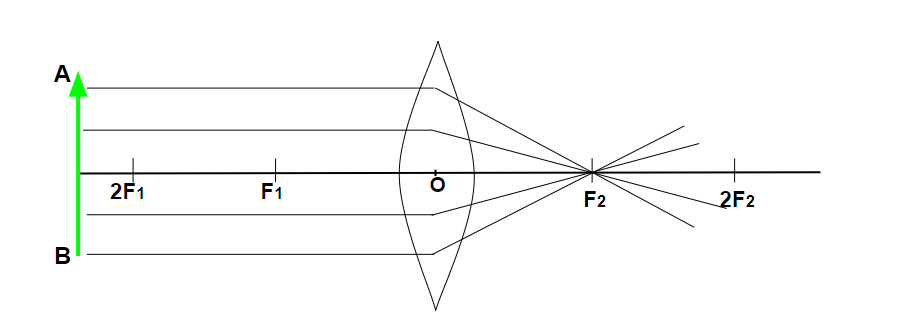
When an object is at infinity:
When object AB (shown in the figure below) is placed at infinity that is behind the 2F1 of the convex mirror, the image formed after the refraction will on focus F2 which is on the opposite side of the convex lens. The size of the image is smaller than the object and the image will be real and inverted(i.e upside down and downside up).
- The image formed at – Focus (F2)
- The nature of the image formed – Real and inverted
- The size of the image formed – Diminished (smaller)
When an object is at infinity, the image is formed at Focus (F2).
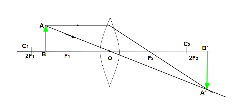
When an object is placed behind the Centre of Curvature (C1):
When the object is placed behind the centre of curvature (C1) or behind Focus (2F1) of the convex lens, the image formed after the refraction will be between the foci of another side of the lens (i.e. F2 and 2F2). The size of the image is smaller than the object. The nature of the image will be real (can be seen on the screen) and inverted( upside down).
- The image formed at – Between 2F2 and F2.
- The nature of the image formed – Real and inverted
- The size of the image formed – Diminished (smaller)
When an object is placed behind the Centre of Curvature (C1), the image is formed between 2F2 and F2.
When the object is placed at the centre of curvature (C1 or 2F1):
When an object is placed at the centre of curvature (C1) or focus (2F1) of the convex lens, the image formed after the refraction will be on the centre of curvature (C2) or focus (2F2) on the other side of the lens. The size of the image is the same as the size of the object. The nature of the image is real and inverted.
- The image formed at – C2 or 2F2.
- The nature of the image formed – Real and inverted
- The size of the image formed – Equal to the object size.
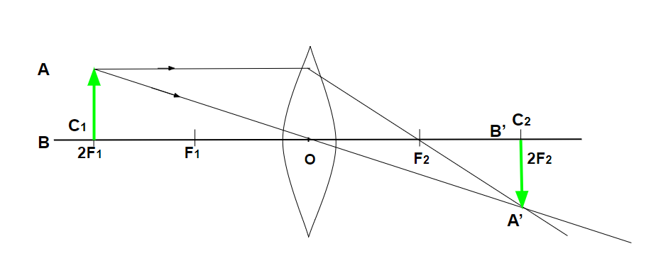
When the object is placed at the centre of curvature (C1 or 2F1), the image is formed at C2 or 2F2.
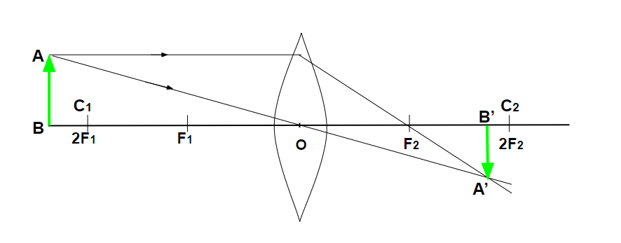
When the object is placed between 2F1 and F1:
When an object is placed between the centre of curvature and the focus (F1) of the convex lens, the image formed after reflection will be behind the centre of curvature (C2). The size of the image will be greater than the object. The nature of the image will be real and inverted.
- The image formed at – Behind centre of curvature (C2)
- The nature of the image formed – Real and inverted
- The size of the image formed – Enlarged
When the object is placed between 2F1 and F1, the image is formed behind the centre of curvature (C2).
When the object is placed at focus (F1):
When an object is placed at focus (F1) of a convex lens. The image formed after reflection will be at infinity (opposite side of the lens). The size of the object will be much larger than the object. The nature of the image will be real and inverted.
- The image formed at – Infinity (opposite side of the object)
- The nature of the image formed – Real and inverted
- The size of the image formed – Enlarged
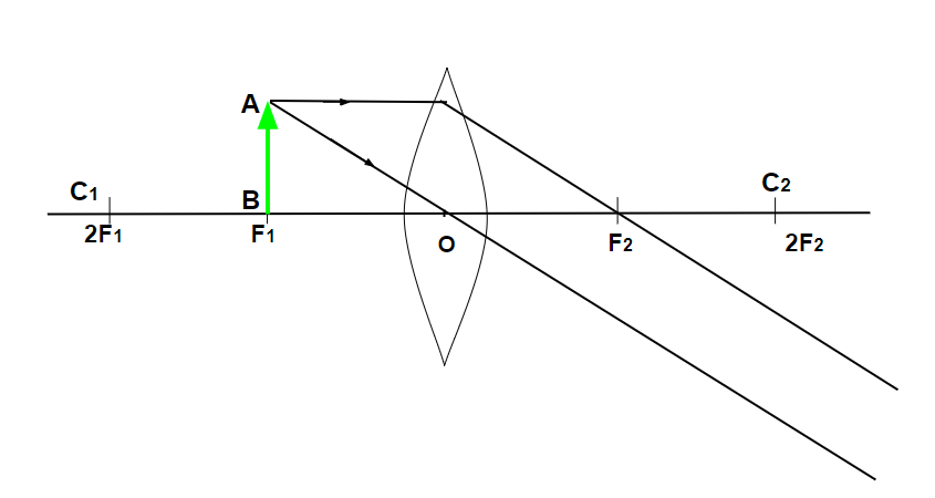
When the object is placed at focus (F1), the image formed is at Infinity (opposite side of the object).
When the object is placed between pole and focus (O and F1):
When the object is placed between the focus (F1) and the optic centre (O) of the convex lens. The image is formed at the same side of the object behind the centre of curvature (C) or focus (F1) of the lens. The size of the image will be larger than the object. The nature of the image will be Virtual Erect.
- The image formed at – At the same side of the object behind 2F2.
- The nature of the image formed – Virtual and Erect.
- The size of the image formed – Enlarged
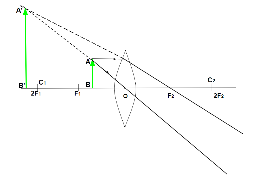
When the object is placed between pole and focus (O and F1), the image formed is at the same side of the object behind 2F2.
Image formed by Concave lens
There are only two different cases for the image formation by a concave lens, which are discussed as:
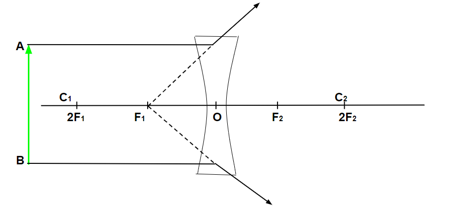
When the object is placed at infinity:
When an object is placed at infinity of the concave lens (shown below). The image formed after refraction will be at the focus (F1) on the same side of the object. The size of the image will be much smaller than the object. The nature of the image will be virtual and erect.
- The image formed at – Focus (F1)
- The nature of the image formed – Virtual and Erect
- The size of the image formed – Highly diminished
When the object is placed at infinity, the image formed is at focus (F1).
When the object is placed at a finite distance from the lens:
When the object is placed at any finite distance in front of the concave lens. The image formed after refraction will be between the optic centre (O) and the focus (F) of the concave lens. The size of the image will be smaller than the object.
- The image formed at – Between F1 and optical centre
- The nature of the image formed – Virtual and Erect
- The size of the image formed – Diminished
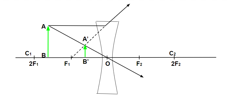
When the object is placed at a finite distance from the lens, the image formed is between F1 and the optical centre.
Sample Questions
Question 1: What is the real image?
Answer:
The image formed when rays of light meet at a certain point after reflection/refraction is real image. Real images can be displayed on screen.
Question 2: What is a virtual image?
Answer:
The image formed when rays of light appear to meet at particular point is called virtual image.
Question 3: What is a ray diagram?
Answer:
The type of diagram which helps to trace the path that light takes in order for a person to view a point on the image of an object is called a ray diagram.
Question 4: What will be the focal length of a lens, if the radius is 16 cm?
Answer:
The focal length is half of the radius of lens, i.e.
f= R / 2
= 16 cm / 2
= 8 cm
Therefore, the focal length will be 8 cm.
Question 5: What will be the focal length of a lens when it is cut along the principal axis?
Answer:
There will be no change in the focal length of a lens when cut into two halves along the principal axis, because the focal length of the lens is half of the radius of curvature and radius of curvature will remain the same.
Dispersion of Light through a Prism
Dispersion of Light happens when white light is split into its constituent hues due to refraction. Dispersion of Light can be achieved through various means but the most common way to achieve dispersion of light is through Prism. Dispersion of light by a prism results in the breaking of white light into its seven constituents.
Dispersion of Light through a prism is achieved by allowing the white light to fall on the prism and passing the light through the prism to break it into its constituent colours. In this article, we will learn about the Dispersion of Light, its experiment and others in detail.
What is Dispersion of Light?
Dispersion is defined as the spitting of white light into different colors when passed through a prism.
The white light after passing through the prism splits into seven different colours namely,
- Violet
- Indigo
- Blue
- Green
- Yellow
- Orange
- Red
Together these colours are written as VIBGYOR.
Learn more about, Dispersion of Light.
Dispersion Of Light Through Prism
When light passes from one medium to another medium speed of propagation of light changes as a result the light is refracted. Now when the light passes through the prism, it gets refracted this refraction of light makes the light split into various colours and this phenomenon is called the dispersion of light through the prism.
Different colours in the light range have different wavelengths. Therefore, the speed at which they bend varies depending on the wavelength, in which the Violet light bends most, and the Red bends the least. As a result, white light coming out from the prism breaks into the spectrum of the light.
Diagram of Dispersion of Light Through Prism
The image below shows the dispersion of light through a prism and the formation of a spectrum by white light.
.webp)
Angle of Deviation
The measure of refraction in the path of light after passing through the prism is measured by measuring the angle of deviation. The angle of deviation is defined as the angle made between the incident ray of light entering the prism and the refracted ray emerging out of the prism.
The deviation of the light waves after passing through the prism is inversely proportional to the wavelength of the light as the wavelength of the Violet light is the least and so the violet light get deviates the most, whereas the wavelength of the red light is the most and hence it gets deviates the least.
The image below shows the angle of deviation:

The visible pattern of the spectrum observed by us when the light passes through the prism is because of the change in the wavelength of the various colour lights.
Visible Light Spectrum
The light disperses into a wide range of colours after passing through a glass prism. We can see this by looking at it from a different perspective. The refractive index associative with a material is not fixed it varies with the frequency of the light used.
- If white light passes a glass prism it gets refracted twice, first when the light strikes the prism the light ray gets deviated from the air to the glass surface and its speed decreases whereas when the light ray leaves the glass prism it again gets deviated from the glass to the air surface and its speed is increased.
- Inside the glass prism, the speed of the light rays remains constant.
- The surface of the prism is not parallel and hence the light ray does not follow the same path and gets deviated.
.png)
This deviation in the white lights makes the spectrum of the light visible and we observe the visible spectrum of the light. For example, the spectrum observed on the oil drop is the visible spectrum of the light.
Prism Experiment
The first experiment of light passing through the prism was first conducted by the great scientist Newton. He allows white light to pass through a prism hoping to get white light to the other end. But to his surprise, he found that white light gets changed to the spectrum of the seven colours. He named this phenomenon as dispersion of light.
Through this experiment, he concluded that light is made up of a spectrum of light. To further prove his experiment he from some other tests as
- He allows the light of only one wavelength to pass through the prism and observes the light ray coming out of the prism and found that this ray only gets refracted and so no sign of dispersion.
- He realized that only white light shows dispersion, as it is made of several colours of light and all these colours of light, have different wavelengths thus their refraction is not the same they all get deviate differently passing through the prism and allowing to form the spectrum of light.
- He concludes that violet light has the shortest wavelength and hence it deviates most whereas red light has the highest wavelength and hence it deviates the least.
Examples of Dispersion of Light
Various examples where the dispersion of light is observed are,
Formation of Rainbow
Dispersion of light is the reason behind the formation of the rainbow. When it rains the tiny water droplets remain in the air. When the sunlight passes through water droplets the light gets dispersed and we see the dispersed light in the form of a Rainbow.
Spectrum observed on Oil Droplets in Water
When oil droplets fall on water, we see the different colours in them. This is because the light undergoes refraction when it passes from the oil to the water medium or vice versa. Hence the light is dispersed and we see the spectrum of different colours in the oil droplets.
Read More,
FAQs on Dispersion of Light
Q1: What is Dispersion of Light?
Answer:
When white light passes through a glass prism, it separates into its spectrum of colours (in order violet, indigo, blue, green, yellow, orange, and red), this process is known as Dispersion.
Q2: What is Prism?
Answer:
A prism is glass apparatus made of transparent glass. It has three rectangular lateral surfaces and two triangular faces that are inclined at an angle. It dispersed the white light passing through it.
Q3:What is Refraction of Light?
Answer:
When the light ray changes its medium of propagation its deviates from its path this phenomenon is called the refraction of the light.
Q4: What is the Difference between Reflection and Refraction of Light?
Answer:
Refraction of light is the change in the direction of light when it changes its propagation of the medium whereas reflection is the change in direction of the light after striking through a solid surface.
Q5: What are Examples of Refraction of Light?
Answer:
Various examples of the refraction of light are,
- Twinkling of Stars
- Formation of Rainbow
- Red light of the sky during sunrise and sunset
Q6: What is VIBGYOR Full Form?
Answer:
When the light ray is passed through the glass prism it gets deviated into the spectrum of the light in the order VIBGYOR and the full form of the VIBGYOR is,
- Violet
- Indigo
- Blue
- Green
- Yellow
- Orange
- Red
0 Comments