
CHAPTER 7 - ALTERNATING CURRENT
AC Voltage Applied to a Resistor
Alternating Currents are used almost as a standard by electricity distribution companies. In India, 50 Hz Alternating Current is used for domestic and industrial power supply. Many of our devices are in fact nothing but resistances. These resistances cause some voltage drop but since the voltage this time is alternating, these voltage drops are dealt with differently. It becomes essential to study the behavior when AC voltage is applied to a resistor.
Alternating Current applied to a Resistor
In the figure given below, an alternating voltage source is shown. It is being applied to a resistor that is connected in series with the source. The source produces a sinusoidal varying potential difference across its terminals. Let us assume that this potential difference is called AC voltage. Then, this sinusoidally varying av voltage can be expressed by the equation given below,
v = vmsinωt
Here, vm is the amplitude of the oscillating voltage and ω denotes its angular frequency.
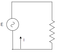
For calculating the value of the current Kirchhoff’s law can be used.
∑ε(t) = 0
Applying this law to the circuit shown above,
v + iR = 0
vmsinωt + iR =0
i = -vm/Rsinωt
So, the amplitude of the current is given by,
i = 
This equation is in compliance with ohm’s law. This means ohm’s law works for both dc and ac voltages. The figure is given below plots both of the values on the graph. Notice that both current and voltage go to maximum and become zero at the same time. This means that they have zero phase difference.
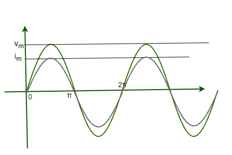
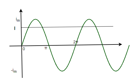
The current also varies sinusoidally like the voltage. It goes on the positive side and increases in magnitude, then again decreases back and changes its direction. It can be inferred from the figure that the average current is also zero in a single cycle is zero.
Power Dissipation
Even though the average current through the cycle is zero, but that does not mean that average power dissipation through the cycle is also zero. Dissipation of electrical energy is there. It’s known that Joule’s heating is given by i2R and depends on i2. This term is always positive irrespective of the sign of “i”. Thus average dissipation cannot become zero.
p = i2R
⇒ p = (imsinωt)2R
⇒ p = (im)2sin2ωtR
This is the instantaneous power in the circuit. Average power dissipation is given by,
pavg = 1/2(im)2R = (vm)2/2R
Expressing this expression of power similar to the usual expression.
pavg = I2R = V2/R
Where  and
and 
This is called the RMS value of the alternating current. For simplicity also, in our households voltages are specified by their RMS value. For example – the 230 V rating is an RMS value, it’s peak value with 311 V.
Sample Problems
Question 1: Find the expression for the current flowing in the circuit with a resistance of 10 ohms. The voltage source works on the expression given, v = 10sin(t)
Answer:
Using Kirchhoff’s law
∑ε(t) = 0
Applying this law to the circuit shown above,
v + iR = 0
10sin(t) + i(10) = 0
i = -sin(t)
Question 2: Find the expression for the current flowing in the circuit with a resistance of 50 ohms. The voltage source works on the expression given, v = 10sin(20t)
Answer:
Using Kirchhoff’s law
∑ε(t) = 0
Applying this law to the circuit shown above,
v + iR = 0
10sin(20t) + i50 = 0
i = -0.2sin(20t)
Question 3: A circuit has two resistors of 20 and 30 ohms respectively. These resistors are connected in series. Find the expression for varying voltage across the 20-ohm resistor if the voltage source is given by, v = 10sin(20t)
Answer:
Since these two resistors are in series, the equivalent resistance will be,
R = 20 + 30
⇒ R = 50
Using Kirchhoff’s law
∑ε(t) = 0
Applying this law to the circuit shown above,
v + iR = 0
10sin(20t) + i50 = 0
i = -0.2sin(20t)
The current through both resistors is same,
Voltage across the 20-ohm resistor is given by,
v = iR.
⇒ v = (-0.2sin(20t))(20)
⇒ v = -4sin(20t)
Question 4: A circuit has two resistors of 50 and 30 ohms respectively. These resistors are connected in series. Find the expression for varying voltage across the 30-ohm resistor if the voltage source is given by, v = 20sin(t)
Answer:
Since these two resistors are in series, the equivalent resistance will be,
R = 50 + 30
⇒ R = 80
Using Kirchhoff’s law
∑ε(t) = 0
Applying this law to the circuit shown above,
v + iR = 0
20sin(t) + i(80) = 0
i = -0.25sin(t)
The current through both resistors is same,
Voltage across the 20-ohm resistor is given by,
v = iR.
⇒ v = (-0.25sin(t))(30)
⇒ v = -7.5sin(t)
Question 5: Average power dissipation in a circuit is given as 400W. The resistance of the circuit is 40 ohms. Find the peak value of the voltage in the circuit.
Answer:
The Average power is given by,
P = V2/R
Given:
V = ?
R = 40
P = 400
plugging these values in the equation,
P = V2/R
⇒ 400 = (V)2 /40
⇒ V = √16000
V = 40√10 V
This is the rms value of the voltage.
Peak Value will be,
V = Vrms√2
⇒ V = 40√20
⇒ V = 80√5 V
Phasors | Definition, Examples & Diagram
Phasor analysis is used to determine the steady-state response to a linear circuit functioning on sinusoidal sources with frequency (f). It is very common. For example, one can use phasor analysis to differentiate the frequency response of a circuit by performing phasor analysis over a range of frequencies. The circuit should be in a stable state so that any transient behavior dies away over time and the response becomes completely repetitive.
In this article, we have provided details about what are phasors, phasor analysis, its Phasors definition, Phasors diagram, and Phasors applications.
Table of Content
What are Phasors?
Phasor analysis computes only the steady-state behavior. The circuit should be linear, which means it is constructed from linear components like simple resistors, capacitors, and inductors. A linear component is one whose response is proportional to its input. For example, a resistor is considered linear if V = IR because voltage V, the response, is proportional to I, the input with the constant of proportionality being R.
- Amplitude,
- Phase
- Frequency.
For example, v(t) = A cos (ωt + φ)
Here A is the amplitude, φ is the phase, and f is the frequency, where ω = 2πf. In a circuit, there will be many signals but in the case of phasor analysis, they will all have the same frequency. Hence, the frequency is differentiated using only their amplitude and phase. This combination of amplitude and phase to describe a signal is the phasor for that signal.
Phasors are a mathematical tool used in engineering and physics to simplify the analysis of sinusoidal signals, which vary cyclically over time. They are instrumental in the study of electrical circuits, electromagnetism, and wave phenomena.
A sinusoidal signal can be expressed in the time domain as A sin(ωt+ϕ) or A cos(ωt+ϕ), where:
- A is the amplitude,
- ω is the angular frequency (in radians per second),
- t is time, and
- ϕ is the phase angle (in radians).
Phasors Definition
A phasor is a complex number used to represent the magnitude and phase of a sinusoidal function, particularly in the context of alternating current (AC) electricity, signal processing, and wave mechanics.
Phasor Diagram
A phasor can be a scaled line whose length determines an AC quantity that has both magnitude (peak amplitude) and direction (phase) which is frozen at some point in time. A phasor diagram is used to show the phase relationship between two or more sine waves having the same frequency. In a phasor diagram, the phasors are represented by open arrows, which rotate counterclockwise, with an angular frequency of ω about the origin.
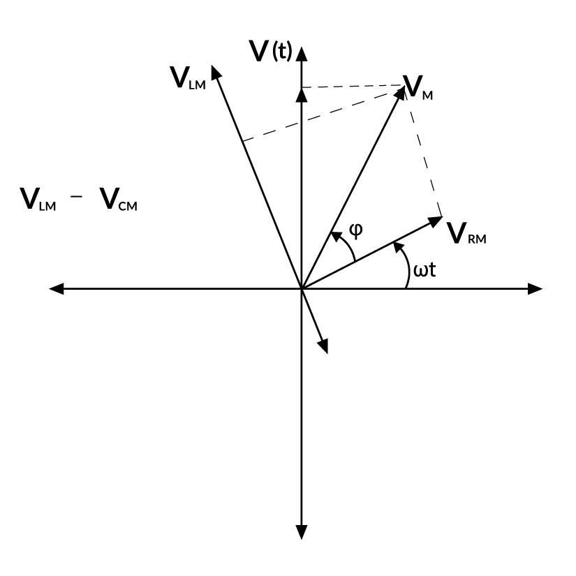
Phasor diagram
Properties of Phasors
- The length of a phasor is proportional to the maximum value of the alternating quantity involved.
- The projection of a phasor on the vertical axis gives the instantaneous value of the alternating quantity involved.
Impedance of AC Circuit
Every component used in the circuit has an internal resistance that depends on the material used for the component. In an AC circuit, the voltage across each electrical component depends on its resistance. For the resistors used in the circuit, the voltage across it is given by Ohm’s law as, VR = I × R where I is the electric current amplitude across the resistor and R is the resistance of the element.
Whereas, in the Resistor-Inductor-Capacitor circuit, the rms voltage is given by the formula: Vrms = Z × Irms where Z is the circuit’s total resistance or the circuit impedance. In other words, the Impedance of the circuit is the total internal resistances of all circuit’s parts used in impeding or slowing down the electric current and thus delaying it from reaching the next circuit’s component. In an AC circuit, the circuit impedance is given by the formula: Z = √(R2 + (XL – XC)2) where XL and XC are the inductive reactance and the capacitive reactance respectively. XL, XC, and Z are all measured in Ohm same as the resistance R.
Application of Phasors in AC Circuits
Phasors are particularly useful in alternating current (AC) circuit analysis because they allow the use of complex algebra to solve circuits. This simplifies calculations involving sinusoidal voltages and currents with different phases. By converting time-domain signals into phasors, one can easily add or subtract voltages and currents, calculate impedances, and solve for unknowns using Ohm’s law and Kirchhoff’s laws in the frequency domain. After the calculations are complete, the results can be converted back to the time domain to interpret physically.
People Also Read:
Phasors Examples
Example 1: The phase difference between the alternating current and voltage represented by the following equation I = I0 sin ωt, E = E0 cos(ωt + π/3), will be
Solution:
Given,
I = I0 sin ωt
E = E0 cos (ωt + π/3)
= E0 sin (π/2 + (ωt + π/3)) …{since, sin((π/2) + θ = cosθ}
= E0 sin (ωt + 5π/6)
So, phase difference (φ) = 5π/6
Example 2: A coil of 200 Ω resistance and 1.0H inductance is connected to an ac source of frequency 200/2π Hz. Phase angle between potential and current will be.
Solution:
We know,
tanφ = Xl / R = 2πvL/R = (2π x 200/2π x 1)/ (200) = 1
Hence, φ = 45o.
Example 3: The current through a coil of self-inductance L = 2mH is given by i = t2e-t at time t. How long it will take to make the emf zero?
Solution:
The current is given by the relation i = t2e-t.
When the emf is zero, the current (i) will also be zero.
so we have t2e-t = 0
we set each factor equal to zero separately:
- t2 = 0 : when t=0 ,it’s not the solution because it’s the starting point.
- e-t = 0 : Exponential functions never equal zero, so this factor is not the solution.
the only solution is t = 0, which means the emf becomes zero at t = 0 . This is the starting time.
Example 4: The phase difference between the alternating current and voltage represented by the following equation I = I0 sin ωt , E = E0 cos(ωt + π/3), will be
Solution:
Given:
I = I0 sin ωt
E = E0 cos (ωt + π/3)
= E0 sin [π/2 + (ωt + π/3) ] {sin( π/2 + θ) = cosθ}
= E0 sin (ωt + 5π/6)
So, phase difference (φ) = 5π/6
Example 5: The phase difference between current and voltage is an AC circuit is π/4 radian. If the frequency of AC is 50 Hz, then the phase difference equivalent to the time difference is.
Solution:
Given:
Phase difference (φ) = π/4 rad
Frequency (f) = 50Hz
Then,
time difference (Δt) = φ / 2πf
Δt = π/4 / 2π x 50 = 1/400 = 0.0025 s
Δt = 2.5 ms
Example 6: The instantaneous values of current and emf in an ac circuit are I = (1/√2) sin 314t amp and E = √2sin(314t – π/6)V respectively. The phase difference between E and I will be.
Solution:
We know that,
Phase difference relative to the current,
φ = (314t – π/6) – (314t)
= – π/6
Example 7: A 12 Ω resistor and a 0.21 H inductor are connected in series to an a.c. source operating at 20 V. 50 cycles/second. The phase angle between the current and source voltage is
Solution:
Given:
Resistance (R) = 12 Ω
Inductance (I) = 0.21 Henry
Hence, ω = 2πf = 2π x 50 = 100π
ωL = 100π x 0.21 = 66 Ω
Reactance (Z) = √(R2 + (XL)2) = √(R2 + (ωL)2) = √(144 + 4356) = √4500 = 67.08Ω
Power factor, cos φ = R / Z = 12/67.08 = 0.1789
Phase angle = φ = cos-1(0.1789) =79.70 which is the lagging phase angle between the current and source voltage.
Important Physics Related Links:
- Charge Definition Physics
- Nand Gate To Or Gate
- Refraction Diagram
- What Is Gravitation
- Rear View Mirror Concave Or Convex
- What Is A Projectile
- Young’s Modulus Of Wood
- Inertial Frame
- Conventional Sources Of Energy Examples
- Rms Value Formula
Summary – Phasors
Phasors are an invaluable mathematical tool in engineering and physics, especially when it comes to analyzing circuits that operate with sinusoidal signals — think waves of electricity that ebb and flow over time. Imagine trying to understand a conversation where everyone speaks at the same tone but with varying loudness and timing; that’s similar to how phasors help engineers differentiate signals in a circuit. They boil down the complex dance of alternating current (AC) signals to simpler terms of magnitude and phase, ignoring the frequency since it’s uniform across the board.
Phasors transform these signals from the time realm into a more manageable frequency domain, letting us visually represent the relationship between signals as vectors or arrows in a phasor diagram. This graphical approach, along with phasor algebra, streamlines calculating how different parts of an AC circuit, like resistors, capacitors, and inductors, affect the overall flow of electricity.
By understanding the impedance, or the total resistance within the circuit, engineers can predict how electricity behaves, making phasors essential for designing and troubleshooting everything from household electronics to complex power grids.
Phasors – FAQs
Define Phasor?
A phasor is a complex number used to represent the magnitude and phase of a sinusoidal function, particularly in the context of alternating current (AC) electricity, signal processing, and wave mechanics.
What are Phasor diagrams?
Phasor diagrams present a graphical representation, plotted on a coordinate system, of the phase relationship between the voltages and currents within passive components or a whole circuit. Generally, phasors are defined relative to a reference phasor which is always points to the right along the x-axis.
How to calculate circuit impedance?
To Calculate the circuit impedance (Z):
Step 1: Find the capacitor’s impedance XC and the inductor’s impedance XL then do the subtraction XL – XC.
Step 2: Square the difference (XL – XC) and add it to the square value of the resistance R.
Step 3: Square root the end result to get Z measured in Ohms.
Explain the uses of the Phasor diagram.
Uses of phasor diagram are:
- Vectors, Phasors and Phasor diagrams can only be applied to sinusoidal AC alternating quantities.
- Phasor Diagrams can be used to represent two or more stationary sinusoidal quantities at any instant in time.
- Phasor diagrams can be drawn to represent more than two sinusoids. They can be either voltage, current or some other alternating quantity but the frequency of all of them must be the same.
How to draw a phasor diagram?
There are Five Rules for Drawing Phasor Diagrams.
Rule 1: The length of the phasor is directly proportional to the amplitude of the wave depicted.
Rule 2: In circuits which have L, C, R connected in series. It is customary to draw the phasor representing current horizontally, and call this the reference phasor.
Rule 3: In parallel circuits, where L, C, and R are connected in parallel, the phasor representing the supply voltage is always drawn in the reference direction.
Rule 4: The direction of rotation of all phasors is considered to be Anticlockwise.
Rule 5: In any one diagram, the same type of value (RMS, peak, etc) is used for all phasors, not a mixture of values.
How are Phasor diagrams used to denote Phase Difference?
Every phasor in the diagram will have the same angular velocity because they represent sine waves of identical frequency. The length of the each phasor arm is directly related to the amplitude of the wave it represents, and the angle between the phasors is the same as the angle of phase difference between the sine waves.
AC Voltage Applied to an Inductor
Alternating Currents and Voltages vary and change their directions with time. They are widely used in modern-day devices and electrical systems because of their numerous advantages. Circuits in everyday life consist of resistances, capacitors, and inductances. Inductors are devices that store energy in their magnetic fields when current flows through them. These devices are found in a lot of applications so it is essential to understand the behavior of the circuit when capacitance is connected to a voltage source. Let’s look at these concepts in detail.
AC Voltage Applied to an Inductor
The figure given below shows an ac circuit. Here, an ac voltage source is connected to a capacitor. The expression for the voltage from the voltage source is given by v = vmsin(ωt). An inductor is a passive electrical device that stores energy when the magnetic field is created inside due to the flowing electric current. Inductor either acquires or losses charge. The effect of the inductor is called inductance. An inductor when connected to a voltage source draws current from the source so as to charge itself.
The voltage across an inductor is measured by the change in electric current through the inductor.
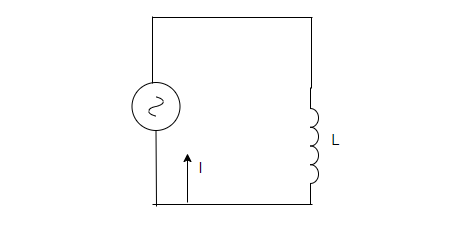
In the circuit given above, an inductor is connected to an alternating voltage source denoted by ~. Assuming that the resistance in the windings is negligible. As the current changes, the inductor acquires potential. The circuit is a purely inductive circuit.
Using the kirchhoff’s rule,

The second term in the equation is the self-induced emf inside the inductor. Let the inductance be denoted by “L”.

This is an equation in terms of current. It is expressed in terms of derivatives. The slope of the current is varying with time. To obtain the value of the current, the equation must be integrated.

⇒ 
The integral constant has dimensions of current and is time-independent. Since the emf voltage source oscillates symmetrically around zero, the current in the circuit also oscillates so that no time independent exists. Thus, the value of the constant is zero.

Rearranging the above equation,
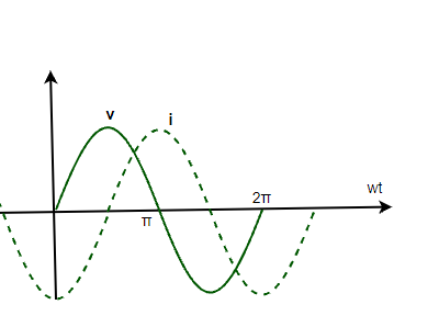
i = imsin(ωt – π/2)
Here, im = vm/ωL. It is the amplitude of the oscillating current. It can also be re-written as,

This equation when compared to ohm’s law gives ωL as resistance. It is called inductive reactance and it is denoted by XL.
Now, the amplitude of the current becomes,
im = 
The dimensions of inductive reactance are the same as resistance and its SI unit is Ohms. Intuitively speaking, inductive reactance limits the current of a purely inductive circuit in the same way as resistance limits the current in a usual resistive circuit.
Previous equations show that the current is behind the voltage in terms of phase. There is a phase difference of  . The figure given below shows the variation of voltage and current with time.
The power dissipated in a purely inductive circuit can be derived using the instantaneous equation of power,
Pc = iv
⇒ Pc = (imsin(ωt – π/2))(vmsin(ωt))
⇒ Pc = -imvmcos(ωt)sin(ωt)
⇒ Pc = – imvm/2sin(2ωt)
The average power dissipated in this case,
Pav = 0
Sample Problems
Question 1: A inductor of 12mH is connected to a voltage source of frequency 50Hz. Find the reactance of the inductance.
Answer:
The reactance of the inductance is given by,
XL = ωL
Given:
f = 50Hz
L = 12 mH
ω = 2πf
⇒ ω = 2π(50)
⇒ ω = 100π
Plugging the values in the equation,
XL = ωL
⇒ XL = 100π × 12 × 10-3
⇒ XL = 1200π × 10-3
⇒ XL = 37.7 × 10⁻³
⇒ XL = .0377 Ohms
Question 2: A inductor of 24mH is connected to a voltage source of frequency 50Hz. Find the reactance of the inductance.
Answer:
The reactance of the inductance is given by,
XL = ωL
Given:
f = 50Hz
L = 24 mH
ω = 2πf
⇒ ω = 2π(50)
⇒ ω = 100π
Plugging the values in the equation,
XL = ωL
⇒ XL = 100π × 24 × 10-3
⇒ XL = 2400π × 10-3
⇒ XL = 75.4 × 10⁻³
⇒ XL = .0754 Ohms
Question 3: A capacitor of 1 mH is connected to a voltage source given by,
v = 50sin(20t)
Find the amplitude of the current.
Answer:
The reactance of the capacitance is given by,
XC = ωL
Given:
ω = 20
L = 1 mF
Plugging the values in the equation,
XL = ωL
⇒ XL = 0.02
Amplitude of the current will be,
im = vm/Xc
⇒ im = 50 / (0.02)
⇒ im = 5000A
Question 4: A sinusoidally varying current is applied to an inductive circuit. The impedance of the inductance is given as 2 ohms. Find the power dissipated in the circuit if the voltage source has an RMS voltage of 45V.
Answer:
The Average power is given by,
P = VIcos(φ)
Since the circuit is purely inductive circuit. The, phase angle will be 90°.
cos(φ) = 0
plugging the values in the equation,
P = VIcos(φ)
P = 0.
Question 5: A capacitor of 10mH is connected to a voltage source given by,
v = 50sin(20t)
Find the amplitude of the current.
Answer:
The reactance of the capacitance is given by,
XL = ωL
Given:
ω = 20
L = 10mH
Plugging the values in the equation,
XL = ωL
⇒ XL = 20 × 10 ×10-3
⇒ XC = 0.2
Amplitude of the current will be,
im = vm/Xc
⇒ im = 50 / (0.2)
⇒ im = 100A
AC Voltage Applied to a Capacitor
Alternating Currents and Voltages vary and change their directions with time. They are widely used in modern-day devices and electrical systems because of their numerous advantages. Circuits in everyday life consist of resistances, capacitors, and inductance. Capacitors are the devices that accumulate charges on their plates and store the charges. It is essential to understand the behavior of the circuit when capacitance is connected to a voltage source.
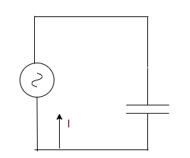
AC Voltage Applied to a Capacitor
The figure given below shows an AC circuit. Here, an AC voltage source is connected to a capacitor. The expression for the voltage from the voltage source is given by v = vmsin(ωt). A capacitor is an electrical device that stores electrical energy. It is a passive electronic component with two terminals. The effect of the capacitor is known as capacitance. A capacitor when connected to a voltage source draws current from the source so as to charge itself. Once the capacitor is charged, the potential at its plates becomes equal to the potential at the battery. At this point, the current stops flowing into the capacitor. This is called the charging of the capacitor.
In case a charged capacitor is put in a circuit where the potential at the plates of the capacitors is greater than the potential at the voltage source. In that case, the capacitor starts acting like a voltage source with varying voltage. The current starts flowing from the capacitor and thus decreasing the charge on its plates. This is called discharging of the capacitor.
In the circuit given above, the current will flow for a short time during which the capacitor charges. As it charges, the current decreases. In situations where a capacitor is connected to an ac source, it regulates the current but does not completely prevent the flow of charge. The capacitor is alternately discharged and charged as the direction of the current is reversed at every half cycle.
At a particular time “t”, denotes the charge on the capacitor by “q”. The instantaneous voltage across the capacitor is given by,

Using the kirchhoff’s rule,

Since the current is continuously changing, to find the current. Derivative of the charge is required,
Differentiating the given equation,

⇒ 
⇒ 
i = vmωC cos(ωt)
Rearranging the above equation,
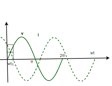
i = imsin(ωt + π/2)
Here, im = vmωC. It is the amplitude of the oscillating current. It can also be re-written as,

This equation when compared to the ohm’s law gives 1/ωC as resistance. It is called capacitive reactance and it is denoted by XC.
Now, the amplitude of the current becomes,
im = 
The dimensions of capacitive reactance are the same as resistance and its SI unit is Ohms. Intuitively speaking, capacitive reactance limits the current of a purely capacitive circuit in the same way as resistance limits the current in a usual resistive circuit.
Previous equations show that current is ahead of voltage in terms of phase. There is a phase difference of π/2. The figure given below shows the variation of voltage and current with time.
The power dissipated in a purely capacitive circuit can be derived using the instantaneous equation of power,
Pc = iv
⇒ Pc = (imsin(ωt + π/2))(vmsin(ωt))
⇒ Pc = imvmcos(ωt)sin(ωt)
⇒ Pc = imvm/2sin(2ωt)
The average power dissipated in this case,
Pav = 0
Sample Problems
Question 1: A capacitor of 12pF is connected to a voltage source of frequency 50Hz. Find the reactance of the capacitance.
Answer:
The reactance of the capacitance is given by,
XC = 1/ωC
Given:
f = 50Hz
C = 12 pF
ω = 2πf
⇒ ω = 2π(50)
⇒ ω = 100π
Plugging the values in the equation,
XC = 1/ωC
⇒ XC = 1/(100π × 12 × 10-12)
⇒ XC = 1/(12π × 10-10)
⇒ XC = 0.0265 × 10¹⁰
⇒ XC = 2.65 × 10⁸ Ohms
Question 2: A capacitor of 24pF is connected to a voltage source of frequency 50Hz. Find the reactance of the capacitance.
Answer:
The reactance of the capacitance is given by,
XC = 1/ωC
Given:
f = 50Hz
C = 24 pF
ω = 2πf
⇒ ω = 2π(50)
⇒ ω = 100π
Plugging the values in the equation,
XC = 1/ωC
⇒ XC = 1/(100π × 24 × 10-12)
⇒ XC = 1/(24π × 10-10)
⇒ XC = 0.01325 × 10¹⁰
⇒XC = 1.325 × 10⁸ Ohm
Question 3: A capacitor of 1000 pF is connected to a voltage source given by,
v = 50sin(20t)
Find the amplitude of the current.
Answer:
The reactance of the capacitance is given by,
XC = 1/ωC
Given:
ω = 20
C = 10pF
Plugging the values in the equation,
XC = 1/ωC
⇒ XC = 1/(20 × 1000 ×10-12)
⇒ XC = 1/(2 × 10-8)
⇒ XC = 0.5 × 10⁸
⇒ XC = 5 × 10⁷ Ohm
Amplitude of the current will be,
im = vm/Xc
⇒ im = 50 / (5 × 10⁷)
⇒ im = 10-6A
Question 4: A sinusoidally varying current is applied to a capacitive circuit. The impedance of the capacitance is given as 2 ohms. Find the power dissipated in the circuit if the voltage source has an RMS voltage of 45V.
Answer:
The Average power is given by,
P = VIcos(φ)
Since the circuit is purely capacitive circuit. The phase angle will be 90°.
cos(φ) = 0
Plugging the values in the equation,
P = VIcos(φ)
P = 0.
Question 5: A capacitor of 10pF is connected to a voltage source given by,
v = 50sin(20t)
Find the amplitude of the current.
Answer:
The reactance of the capacitance is given by,
XC = 1/ωC
Given:
ω = 20
C = 10pF
Plugging the values in the equation,
XC = 1/ωC
⇒ XC = 1/(20 × 10 ×10-12)
⇒ XC = 1/(2 × 10-10)
⇒ XC = 0.5 × 10¹⁰
⇒ XC = 5 × 10⁹ Ohm
Amplitude of the current will be,
im = vm/Xc
⇒ im = 50 / (5 × 10⁹)
⇒ im = 10-8A
Series LCR Circuits
In contrast to direct current (DC), which travels solely in one direction, Alternating Current (AC) is an electric current that occasionally reverses direction and alters its magnitude constantly over time. Alternating current is the type of electricity that is delivered to companies and homes, and it is the type of electricity that is used by consumers when they plug in kitchen appliances, televisions, fans, and electric lamps to a wall outlet. A flashlight’s battery cell is a frequent source of DC power. When modifying current or voltage, the abbreviations AC and DC are frequently used to signify merely alternating and direct.
In most electric power circuits, the most common waveform of alternating current is a sine wave, whose positive half-period correlates to the positive current direction and vice versa. The current may not truly reverse direction (as for the labeled pulsating waveform). Different waveforms, such as triangle waves or square waves, are employed in various applications, such as guitar amplifiers. Alternating current also includes audio and radio signals transmitted by electrical lines. Information like sound (audio) or images (video) is occasionally transmitted via modulation of an AC carrier signal in these forms of alternating current. The frequency of these currents is usually higher than that of power transmission currents.
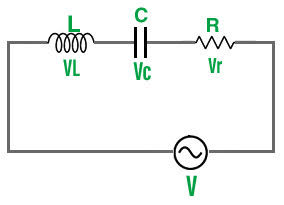
Series LCR Circuit
An LCR circuit is made up of three components: an inductor (L), a capacitor (C), and a resistor (R). A tuned or resonant circuit is another name for it. A series LCR circuit is made up of these devices that are connected in series. As a result, the resistor, capacitor, and inductor will all have the same amount of current flowing through them.
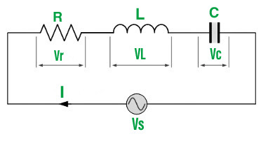
A voltage VS is applied across the LCR series circuit in the above circuit, which depicts a simple LCR series circuit.
Impedance is the amount of resistance a circuit provides to current flow. It’s the effective resistance to alternating current flow in an electric circuit made up of numerous electric components. It is caused by the interaction of ohmic resistance, capacitive reactance, and inductive reactance. If R denotes resistance, XL denotes inductive reactance, XC denotes capacitive reactance, then Z denotes impedance.
Z=√ R2+(XC−XL)2
Derivation for AC Voltage applied across Series LCR Circuit
An inductor (L), capacitor (C), and resistor (R) are linked in series in the electrical circuit, which is powered by an AC voltage supply. The alternating voltage V is supplied by the voltage source, where
V=Vm sin(ωt)
where,
- Vm is the amplitude of the applied voltage, and
- ω is the frequency of the applied voltage.
If q is the charge on the capacitor and I is the current flowing in the circuit at any moment t, the voltage equation for the circuit can be written as follows:
Net EMF across the circuit: V (source voltage) = Voltage drop across resistor + Voltage drop across capacitor + Self-induced Faraday’s emf in the inductor
V=L(di/dt) + IR + q/C
The inductor’s self-inductance is denoted by L.
Substituting alternating voltage for the expression,
Vm sin(ωt) = L(di/dt) + IR + q/C …..(1)
Let us use the analytical method to determine the instantaneous current I or its matching phase to the applied alternating voltage V. We know that current is equal to the rate at which electric charge flows per unit of time, i.e.,
I=dq/dt
Differentiating both sides with respect to time, we get:
dI/dt=d2q/dt2
The voltage equation in terms of q is obtained by substituting the above value into equation (1):
Vm sin(ωt) = L(d2q/dt2) + (dq/dt)R + q/C ……(2)
The equation for a forced or damped harmonic oscillator is similar to this equation.
q = qm sin(ωt+θ)
Differentiating both sides with respect to time,
dq/dt = qm ωcos(ωt+θ)
d2q/dt2=–qm ω2sin(ωt+θ)
Substituting these values in equation (2),
Vm sin(ωt) = qm ω [Rcos(ωt+θ) + (XC–XL)sin(ωt+θ)] …..(3)
Here,
- Capacitive reactance: XC=1/ωC
- Inductive reactance: XL=ωL
- Impedance: Z= √R2+(XC−XL)2
Substituting the above values in equation (3), so we get:
Vm sin(ωt)=qm ωZ[R/Z cos(ωt+θ) + (XC–XL)/Zsin(ωt+θ)] ……(4)
Consider,
R/Z = cos∅
(XC–XL)/Z = sin∅
Dividing the two equations:
(XC–XL)/R=tan∅
∅=tan–1((XC–XL)/R)
Substituting the above values in equation (4):
Vm sin(ωt)=qm ωZ[cos(ωt+θ–∅)]
Comparing the LHS and RHS of this equation, we get
Vm=qm ωZ=Im Z
The current in the LCR circuit,
I=dq/dt
or,
I = qm ωcos(ωt+θ)
I = Im cos(ωt+θ) [where, qm ω=Im]
Since, θ–∅= – π/2
θ= – π/2 + ∅
We get,
I = Im cos(ωt–π/2+∅)
I = Im sin(ωt+∅)
Here, Im=Vm/Z = Vm / √R2+(XC–XL)2 and ∅=tan–1(XC–XL/R)
- Thus, for θ=0∘ , As a result, the applied voltage and instantaneous current are in phase
- For θ=90∘ , The applied voltage is out of phase with the instantaneous current.
Resonance of LCR Circuit
If the output of a circuit reaches its maximum at a specific frequency, it is said to be in resonance. The resonance phenomenon is connected with systems that have a tendency to oscillate at a specific frequency known as the natural frequency of the system. The amplitude of oscillation is observed to be considered when an energy source drives such a system at a frequency close to the natural frequency.
We discovered that the amplitudes of voltage, frequency, and current are related to each other in the following series of LCR circuits:
Im = Vm/Z = Vm / √R2+(XC–XL)2
where,
- XC=1/ωC and
- XL=ωL
Im=Vm/Z=Vm / √R2+(1/ωC−ωL)2
When the circuit’s impedance is low, the current flowing through it is at its maximum. To accomplish so, we change the frequency value till we have XC=XL at a given frequency of ω0 and the impedance,
Z=√ R2+(XC−XL)2 = √ R2+0 = R
Thus, the current will be maximum, i.e.,
I=Vm/R
When the series LCR circuit’s impedance, Z=R, equals the resistance. This frequency ω0 is referred to as the circuit’s resonant frequency.
For, XC=XL
1/ω0C=ω0L
Or,
ω0 = 1/√LC
Resonance occurs in a series LCR circuit when the capacitive and inductive reactances are equal in magnitude but 180 degrees apart in phase.
For the series LCR circuit, the phase difference,
∅=tan–1(XC–XL / R)
For, XC=XL , ∅=0, the circuit is in resonance.
XC>XL , ∅<0, the circuit is predominately capacitive
XC<XL , ∅>0, the circuit is predominately inductive
Circuit Power Factor: The ratio of active power to total power is used to define the power of an AC circuit. i.e.
Power Factor, CosΦ=Active power/Total Power
CosΦ=I2R / I2Z
=R/Z
=R / √(R)2+(XL−XC)2
Power Consumed: The resistor is the sole component in the circuit that consumes power; the inductor and capacitor do not. Therefore,
P=VI CosΦ
=(IZ)×I×R/Z
=I2R
Q – Factor of Series Resonant Circuit: The circuit’s Q-factor (Quality Factor) is defined as the ratio of reactive to active power, i.e.
Q−factor = Reactive Power/Active Power
Q−factor = I2XL/I2R = =I2Xc/I2R
Q−factor= ωL/R = 1/ωCR
At resonance,
ω0=1/√LC
So,
Q0−factor=1/R × √L/C
Sample Problems
Problem 1: In a series RLC, circuit R = 30 Ω, L = 15 mH, and C = 51 μF. If the source voltage and frequency are 12 V and 60 Hz, respectively, what is the current in the circuit?
Solution:
XL = 2 × 3.14 × 60 × 0.015 = 5.655 Ω
XC = 1/ 2 × 3.14 × 60 × 0.000051 = 5.655 Ω
Z = √(30)2 + (52-5.655)2 = 55.21 Ω
I = 12/55.21 = 217 mA
Problem 2: A series RLC circuit consists of a 20 Ω resistor, a 51 μF capacitor, and a 25 mH inductor. If the source frequency is 50 Hz, and the circuit current is 350 mA, what is the applied voltage?
Solution:
Given that,
R =20 Ω
XL = 2 × 3.14 × 50 × 0.025 = 7.85 Ω
XC = 1/ 2 × 3.14 × 50 × 0.000051 = 62.445 Ω
Z= √(20)2 + (7.85-62.445)2 = 58.15 Ω
V= IZ = 58.15 × 0.35 = 20 V
Problem 3: A 240 V, 50 Hz AC supply has applied a coil of 0.08 H inductance and 4 Ω resistance connected in series with a capacitor of 8 μF. Calculate the Impedance
Solution:
Here,
XL= ωL = 2πfL=2π×50×0.08=25.12 Ω
XC=1/ωC=1/2πfL=1/2π×50×8×10−6= 398.09 Ω
Thus,
Impedance of the circuit
Z=√(R)2+(XL−XC)2
= √(4)2+(25.12−398.09)2
= 372.99 Ω
Conceptual Questions
Question 1: What is the resonance condition for the series LCR circuit?
Answer:
The capacitive and inductive reactances are equal and 180 degrees out of phase at resonance.
Question 2: What is the impedance of the series LCR circuit?
Answer:
The combined effects of ohmic resistance and reactance produce the effective resistance of an electric circuit or component to alternating current.
The impedance of a series LCR circuit is expressed as,
Z=√R2+(XC−XL)2
Question 3: What is the sharpness of resonance?
Answer:
The Q factor determines the sharpness of resonance.
- The Q factor is a dimensionless parameter that describes the energy losses in a resonant element, such as a mechanical pendulum, a mechanical structure element, or an electronic circuit such as a resonant circuit.
- Q is frequently used in conjunction with an inductor.
- The sharpness of resonance is proportional to the rate at which the oscillating system’s energy decays.
Power Factor in AC circuit
The power factor is determined by the cosine of the phase angle between voltage and current. In AC circuits, the phase angle between voltage and current is aligned, or in other words, zero. But, practically there exists some phase difference between voltage and current. The value of the power factor always lies between 0 and 1. For a purely capacitive circuit, it is 0 and for the purely resistive circuit, it is 1. whereas, there is no power factor in DC circuits due to zero frequency. It is used to measure how effectively the incoming power is used in an electrical system(energy efficiency).
Table of Content
Power Factor
Power factor is defined as the ratio of real power to the apparent power.
The formula for the power factor is given below :
Power Factor = cosФ = Real power/Apparent power
Real Power - The capacity of the electricity for performing work. It is also known as true power, active power, and working power. It is measured in kilowatts(kW).
Apparent Power - The combination of real power and reactive power. It is also known as total power. It is measured in kilovolt amperes(kVA).
Different Types of Power in AC Circuit
Instantaneous Power: It is defined as the product of voltage across the element and instantaneous current through the element at any instant of time. It is denoted by the letter P. The rate at which an element absorbs energy (in watts).
P=V x I
.webp)
where, V and I are the instantaneous voltage and current. Since
    V=V msinωt
    I=I m sin(ωt-Ф).
Then the instantaneous power at any time t can be expressed as
    P=V m I msinωtsin(ωt-Ф)
By using trigonometric identity,
     sin(ωt-Ф)=sinωtcosФ-cosωtsinФ
The power becomes:
      P instantaneous = V m I m cosФsin2ωt - V m I m sinФsinωt cosωt
Averaging this power over a complete cycle gives the average power.
Average Power: It can be calculated by calculating the instantaneous power of the circuit. As the instantaneous power continuously fluctuates over time, calculating the average requires integration. By averaging over a single period (T) of the sinusoidal function, the average power can be determined. The second term in the expression averages to zero. It is an odd function of t. The average of the first term is given by
P average = V m I m cosФ ∫T0 sin2ωtdt  ∕  T
               =V m I m cosФ ∕  2
Since the rms voltage and current are given by
V = V m  ∕  √2  and I = I m  ∕  √2
The average power can be expressed as
P average = VI cosФ
Apparent Power: The product of the rms voltage and rms current is called apparent power. The apparent power is the same as the real power when the impedance is a pure resistance. The apparent power is greater than real power when reactance exists. It is measured in kilovolt amperes(kVA). It is denoted by letter S.
Reactive Power: The power that corresponds to storage and retrieval of energy rather than consumption. It is measured in kilovolt-Ampere reactive (k VAR).It is denoted by letter Q.
Power triangle represents the real power, reactive power and apparent power of the AC circuit in the right-angle triangle. It shows the relationship between all three powers.
.webp)
Real power, P = VI cosФ
Reactive power, Q = VI sinФ
Apparent power, S = VI [S2 = P2 + Q2 ]
Complex Power: It is the vector sum of real power and reactive power.
S = P + Q j
Problem 1. Given a circuit with an apparent power of 600VA and a real power of 300W, calculate the power factor.
Given,
Real power = 300W
Apparent power = 600VA
To find power factor ,
Power Factor =  Real power/Apparent power
                         = 300 / 600
                         = 0.5
Problem 2. In a circuit, the real power is 12W and the reactive power is 5VAR. A Calculate the apparent power and power factor.
Given,
Real power (P) = 12W
Reactive power (Q) = 5VAR
To find the Apparent power(S), by using the relationship between real power, reactive power and apparent power.
S2 = P2 + Q2
S2 = 122 + 52
S2 = 169
S = 13VA[Apparent power]
Now, to find the power factor:
Power Factor = Real power/Apparent power
                         = 12 / 13
                         = 0.923
So, the Apparent power is 13VA and the Power factor is 0.923.
Problem 3. In a circuit, the apparent power is 5VA and the reactive power is 4VAR. Calculate the power factor of the circuit.
Given,
Apparent power(S)= 5VA
Reactive power(Q)= 4VAR
To find Power factor,
Power Factor = Real power/Apparent power
we need the real power to calculate power factor. By using relationship between real power, reactive power and apparent power.
P2 = S2 - Q2
P2 = 52 - 42
P2 = 9
P = 3W[Real power]
Now , we can find power factor
Power Factor = Real power/Apparent power
                         = 3 / 5
                         = 0.6
The power factor of the circuit is 0.6.
Mathematical Analysis
Suppose a voltage V is applied to a LCR circuit, where V is given by :
V = V m sinωt
The current in this case is written by:
I = I m sin(ωt + Ф)
where,
V m = Voltage Amplitude
I m  = Current Amplitude
 ω   = Angular Frequency
 Ф   = Phase Constant
Now, Current Amplitude is related to voltage Amplitude as:
I m = V m  ∕  Z
where , Z = Impedance of circuit and given by:
Z = √(X L - X  C )2 + R2

tanФ = (X L - X  C ) ∕  R

Ф = tan-1(X L - X C ) ∕  R
where,
XL is the inductive reactance(2ЛfL)
XC is the capacitive reactance(1/2ЛfC)
f is the frequency of the AC source.
Problem : In a LCR circuit, the inductance(L) is 0.2 Henry, capacitance(C) is 200 microfarads and the resistance(R) is 30 ohms. The AC source has a frequency of 50Hz.
Given,
Inductance(L) = 0.2 henry
Capacitance(C) = 200 microfarads
Resistance(R) = 30 ohms
Frequency(f) = 50Hz

1. Calculate inductive reactance(XL),
XL= 2ЛfL
XL= (2Л)(50)(0.2)
XL≈ 62.83Ω

2. Calculate capacitance reactance(XC),
XC =1/2ЛfC
XC =1/(2Л)(50)(200x10-6)
XC ≈ 15.91Ω

3. Determine the phase angle(Ф),
Ф = tan-1(X L - X C ) ∕  R
Ф = tan-1(62.83 - 15.91 ) ∕  30
Ф ≈ 1.0019 radians

4. Calculate the power factor(PF),
PF = cos(Ф)
PF = cos(1.0019)
PF ≈ 0.999

So, the power factor of the LCR circuit is approximately 0.999.
Power Consumption in AC Circuit
An electric circuit produces power which is P = V I.
where,
V is voltage across it and
I is the current flowing through the circuit
The Alternating Current(AC) circuits always offer reactance, The power in a circuit has two components, one due to the electric field and the other due to the magnetic field. The average power absorbed by the circuit results from the sum of power stored and returned throughout a complete cycle. Consequently, the average power consumed by the circuit is equivalent to the instantaneous power within a single cycle.
Conclusion
Electrical power is the rate at which energy is consumed inside a circuit. All electrical and electronic devices have a maximum amount of electrical power they can safely handle. In AC circuits, three categories of abilities are there Real power, Reactive power and Apparent power.
Real power is denoted by the letter p and calculated in kilowatts. Whereas reactive power is denoted by letter Q and calculated in kilovolt - ampere reactive. Apparent power is denoted by letter S and calculated in kilovolt - ampere.
A power triangle is the relationship between real power, reactive power and apparent power.
FAQs on Power Factor
What is the difference between real power and reactive power?
Real power is the portion of power in an AC circuit that is converted into useful work, such as generating heat, light, or mechanical energy. Reactive power is the power oscillating between the source and reactive components(capacitors or inductors) in the circuit.
How can power factor be improved?
It can be improved by adding power factors correction devices such as capacitors, to the electrical system. These devices counteract the reactive power in the circuit, bringing the power factor closer to unity.
What is a Power Triangle?
The Power triangle shows the relationship between Real power, Reactive power and Apparent power and there are denoted by the base, perpendicular and hypotenuse of the right - angled triangle.
Transformer
Transformer is the simplest device that is used to transfer electrical energy from one alternating-current circuit to another circuit or multiple circuits, through the process of electromagnetic induction. A transformer works on the principle of electromagnetic induction to step up or step down voltage. Transformer either increases AC voltage (Step-up transformer) or decreases AC voltage (Step-down transformer). Transformer which is normally utilized in the transmission and distribution of alternating current power is fundamentally a voltage control device. Transformer are used for a wide range of purposes, including increasing the voltage from electric generators to enable long-distance transmission of electricity and decreasing the voltage of conventional power circuits to run low-voltage devices like doorbells and toy electric trains.
What is a Transformer?
A transformer is a static electrical device that transmits AC power from one circuit to another at a constant frequency, but the voltage level may be changed, implying the voltage can be increased or decreased depending on the requirement.
Types of Transformer
Transformer types based on Voltage Level
There are primarily two types of Transformer based on the operating voltage. The following are some of them:
- Step-down Transformer: The primary voltage is converted to a lower voltage across the secondary output using a step-down transformer. The number of windings on the primary side of a step-down transformer is more than on the secondary side. As a result, the overall secondary-to-primary winding ratio will always be less than one. Step-down transformer are used in electrical systems that distribute electricity over long distances and operate at extremely high voltages to ensure minimum loss and economical solutions. Step-down transformer are used to change high-voltage into low-voltage supply lines.
- Step-up Transformer: The secondary voltage of a step-up transformer is raised from the low primary voltage. Because the primary winding has fewer turns than the secondary winding in this sort of transformer, the ratio of the primary to secondary winding will be greater than one. Step-up transformer are frequently used in electronics stabilizers, inverters, and other devices that convert low voltage to a significantly higher voltage. A step-up transformer is also used in the distribution of electrical power. For applications connected to power distribution, high voltage is necessary. In the grid, a step-up transformer is used to raise the voltage level prior to distribution.
Transformer Types based on Core Material
Different types of Transformer are used in the power and electronics industries, depending on the core materials, which are:
- Iron Core Transformer: Multiple soft iron plates are used as the core of an iron core transformer. The iron’s strong magnetic properties of the iron core transformer have extremely high flux linkage. As a result, the iron core transformer has high efficiency. The soft iron core plates come in a variety of sizes and shapes. A few typical shapes include E, I, U, and L.
- Ferrite Core Transformer: Due to its high magnetic permeability, a ferrite core transformer uses one. In the high-frequency application, this kind of transformer provides incredibly low losses. In high-frequency applications like switch mode power supplies (SMPS), RF-related applications, etc., ferrite core transformer are used as a result.
- Toroidal Core Transformer: Iron core or ferrite core are two examples of toroid-shaped core materials used in transformer. For their excellent electrical performance, toroids, which have a ring- or donut-shaped core material, are frequently used. The ring form results in very low leakage inductance and extremely high inductance and Q factors.
- Air Core transformer: The core material of an air core transformer is not a real magnetic core. The air is used solely in the air-core transformer flux linkage. The primary coil of an air-core transformer generates an alternating current, producing an electromagnetic field all around it.
Transformer Types based on Winding Arrangement
- Auto Winding transformer: The primary and secondary windings have always been fixed, but with an auto-winding transformer, they can be connected in series, and the center-tapped node can be moved. The secondary voltage can be altered by changing the location of the central tap. The auto is used to alert the self or a single coil and is not the abbreviation for Automatic. This coil creates a ratio using main and secondary components. The main and secondary ratio is determined by the location of the center tap node, which changes the output voltage. The VARIAC, a device that generates variable AC from a steady AC input, is used the most frequently.
Types of Transformer based on Usage
Transformer come in a wide range of variants, each of which operates in a distinct field. Thus, based on their proposed use, transformer can be categorized as follows:
- Power Transformer: The energy is transferred to the substation or the general electrical supply using a larger power transformer. Between the major distribution grid and the power generator, this transformer serves as a link. Power Transformer can be further divided into three groups based on their power rating and specification-
- Small power transformer,
- Medium power transformer, and
- Large power transformer
- Measurement Transformer: Instrument transformer is another name for measurement transformer. This is yet another measurement tool that is usually utilized in the power domain. To separate the primary power and convert the current and voltage in a smaller ratio to its secondary output, a measuring transformer is used.
- Distribution Transformer: The distribution transformer function as a step-down transformer, converting high grid voltage to the appropriate voltage for the end user, typically 110V or 230V. Depending on the conversion capacity or ratings, the distribution transformer might be less in size or larger.
- Pulse Transformer: One of the most popular PCB-mounted transformer that generates electrical pulses with a consistent amplitude are pulse transformer. It is utilized in a number of digital circuits where the demand for isolated pulse creation exists.
- Audio Output Transformer: Another frequent transformer in the electronics industry is the audio transformer. It is specifically usedin applications involving audio where impedance matching is necessary.
Working Principle of a Transformer
The fundamental principle of how the transformer functions are mutual induction between the two coils or Faraday’s Law of Electromagnetic Induction. Below is a description of how the transformer operates. The laminated silicon steel core of the transformer is covered by two distinct windings. According to the diagram below, the primary winding is the one to which the AC supply is connected, and the secondary winding is the one to which the load is connected. Only alternating current can be used because mutual induction between the two windings requires an alternating flux.
The transformer primary winding produces an alternating flux, known as the mutual flux, when an alternating voltage is applied, in accordance with the mutual inductance principle.
According to Faraday’s rule of electromagnetic induction, this alternating flux links the transformer primary and secondary windings magnetically and generates EMFs E1 in the primary winding and E2 in the secondary winding. The EMF (E1) is referred to as the primary EMF, while the EMF (E2) is the secondary EMF.
and
Dividing above equations, to obtain the ratio as:


From the expression above, it is clear that the size of EMFs E1 and E2 is dependent on the number of turns in the transformer primary and secondary windings, respectively. If N2 > N1, then E2 > E1, and the transformer will be a step-up transformer; if N2 < N1, then E2 < E1, and the transformer will be a step-down transformer.
If a load is now connected across the secondary winding, the load current I2 will flow through the load as a result of the EMF E2. As a result, a transformer makes it possible to transfer electricity with a change in voltage level from one electric circuit to another.
Parts of a Transformer
A transformer majorly consists of three parts:
Core
The transformer core serves as a support for the winding. Additionally, it offers a magnetic flux flow channel with minimal resistance. As seen in the image, the winding is looped around the core. To cut down on losses in a transformer, it has a laminated soft iron core. Core composition is determined by variables including operational voltage, current, and power, among others. The core diameter is negatively correlated with iron losses and directly correlated with copper losses.
Windings
The copper wires that are wound over the transformer core are known as windings. Copper cables are used because Copper’s high conductivity reduces transformer loss because resistance to current flow lowers as conductivity rises. And copper’s high degree of ductility makes it possible to produce incredibly thin wires out of it.
The two basic types of windings are. windings for the primary and secondary coils. The primary winding is the group of winding turns that receive supply current. The number of winding turns from which output is derived is known as secondary winding. Insulation coating agents are used to insulate the primary and secondary windings from one another.
Insulation Agents
Transformer require insulation to keep the windings apart and prevent short circuits. This makes mutual induction easier. Transformer stability and durability are influenced by insulation agents. In a transformer, the following are employed as insulating mediums: Insulating fluid, tape, Paper, and Lamination made of wood.
Tank
A transformer main tank serves two purposes:
- The core and the windings are protected from the elements, such as rain and dust.
- It functions as an oil container as well as a support for all other transformer attachments.
Transformer Oil
The majority of the huge transformer are submerged in oil. The transformer oil adds insulation between the conductors, improves heat dissipation from the coils, and has fault-detecting capabilities. Transformer oil is typically made of hydrocarbon mineral oil.
Oil Conservators
The oil conservator is situated above the transformer tank and bushings. Some transformer oil conservators contain a rubber bladder. When a transformer is loaded, the ambient temperature rises, causing the amount of oil inside the transformer to increase. The transformer conservator tank has enough room for the increased transformer oil. It also serves as a reservoir for oil that is used to insulate buildings.
Breather
All oil-immersed transformer with conservator tank includes it. It aids in the protection of the oil against moisture.
Radiators and Fans
The majority of the power lost in the transformer is dissipated as heat. Radiators and fans aid in the dissipation of heat generated by the transformer and provide protection against failure. The majority of dry transformer are cooled by natural air.
Ideal Transformer
An ideal transformer is a purely theoretical transformer that has no losses at all, including no core losses, copper losses, or other transformer losses. This transformer is thought to be 100% efficient.
The windings of the transformer are assumed to be entirely inductive, and the core of the transformer is assumed to be loss-free when creating the ideal transformer model. Additionally, the transformer has no leakage reactance (reactance is the opposition to the flow of current from the circuit element due to its inductance and capacitance). This indicates that the transformer primary and secondary windings are connected to the core of the transformer at 100% flux. However, every winding must have some inductive resistance that results in voltage drop and I2R loss. In a model of an ideal transformer, the windings are assumed to be perfect (totally inductive), which means that their resistance is zero.
EMF Equation of Ideal Transformer
Let Np is the main winding’s number of turns, whereas Ns is the secondary winding’s number of turns. When an AC voltage is given to the transformer main coil, the current generated creates an alternating magnetic flux that connects the secondary coil and generates an emf. The number of turns in the secondary coil determines the value of this emf. Consider an ideal (lossless) transformer with zero primary coil resistance (no voltage drop across coil) and all flux in the core connecting both primary and secondary windings. When the voltage Vp is delivered to the primary coil, let be the flux linkage in each turn in the core at time t owing to the current in the primary coil.
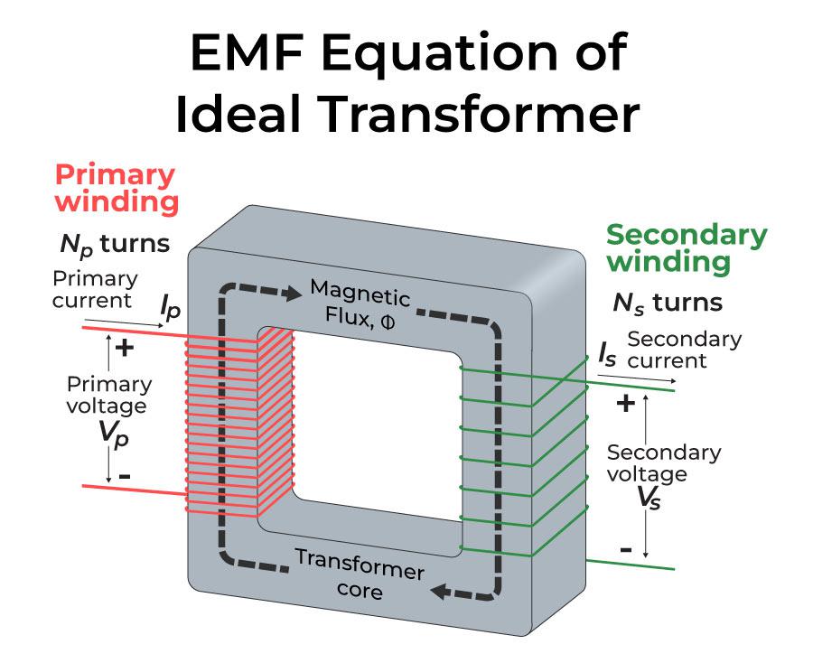
The induced emf or voltage (εs) in the secondary with Ns turns is then calculated.
εs = –Ns x dϕ/dt ……(1)
In addition, the alternating flux generates a reverse emf in the main. This is it.
εp = –Np x dϕ/dt ……(2)
And for an ideal transformer, εp=Vp
By approximation, if the secondary is an open circuit or the current drawn from it is modest, εs=Vs.
The voltage across the secondary coil is Vs. As a result, Equations (1) and (2) may be written as
Vs = –Ns x dϕ/dt ……(3)
Vp = –Np x dϕ/dt ……(4)
From Equations (3) and (4), we have
Vs / Vp = Ns / Np ……(5)
The above equation is known as Transformer Equation or Transformer Formula.
The following three assumptions are used to get the previous relationship:
- The primary and secondary coils’ electrical resistances are insignificant.
- The flux connectivity to both the primary and secondary coils is the same, or very few fluxes escape from the core.
- The secondary current is insignificant.
Turn Ratio
Turn Ratio is a measure to determine whether the secondary coil of a transformer has more or lesser windings than the primary. The number of windings on a primary coil is equal to “Np,” while the number of windings on a secondary coil is “Ns,” representing the number of turns.
The power input and output will be equal if the transformer is perfect or 100 percent efficient (no energy losses).
ipVp = isVs ……(6)
Combining Equations (5) and (6), we have
ip/is = Vs/Vp= Ns/Np=K
The turn ratio, K, is defined in the preceding equation. If the secondary coil has more turns than the primary coil, this is the case (Ns>Np), and the voltage is stepped up (Vs>Vp). A step-up transformer is a name for this sort of setup. A step-down transformer is one in which the secondary coil has fewer turns than the primary coil (Ns<Np).
Efficiency of Transformer
The efficiency of a transformer is also known as commercial efficiency. It is represented by the letter ‘η’. The efficiency of a Transformer is described as the ratio of output (in W or kW) to input (in W or kW).
Hence, the efficiency of transformer may be expressed as follows:
Efficiency (η) = (Power Output / Power Input)
The above equation can be used for an ideal transformer in which there are no transformer losses and all input energy is transferred to the output. As a result, the following equation is mostly used if transformer wastes are taken into account and the efficiency of the transformer is evaluated across the practical states.
Efficiency = ((Power O/P) / (Power O/P + Losses)) × 100%
or
Efficiency = (Power i/p – Losses) / Power i/p × 100 = 1− (Losses/ i/p Power) × 100
Energy Losses in a Transformer
We used an ideal transformer in the previous equations (without any energy losses). However, some energy losses do occur in actual transformer for the following reasons:
- Flux Leakage: Because some flux leaks from the core, not all flux generated by the primary coil make it to the secondary coil. This occurs as a result of the core’s inadequate design or the presence of air holes in the core. It is possible to lower it by wrapping the primary and secondary coils over each other. It can also be lowered if the core is well-designed.
- Windings Resistance: Because the wire used for the windings has some electrical resistance, energy is wasted as a result of the heat generated in the windings. These are mitigated in high current, low voltage windings by utilizing thick wire with a high conductive substance.
- Eddy Currents: The alternating magnetic flux creates eddy currents in the iron core, resulting in energy losses through heating. By using a laminated core, the impact is decreased.
- Hysteresis Loss: In each AC cycle, the alternating magnetic field reverses the magnetization of the core. The loss of energy in the core occurs as heat owing to hysteresis loss, which is minimized by employing a magnetic material with a low hysteresis loss.
Application of Transformer
The following are some of the most common uses for transformer:
- Increasing or reducing the voltage level in an AC circuit to ensure the correct operation of the circuit’s various electrical components.
- It stops DC from flowing from one circuit to another.
- It separates two separate electric circuits.
- Before transmission and distribution can take place, the voltage level at the electric power plant must be increased.
Also Check:
Solved Examples on Transformer
Example 1: A transformer primary winding is powered by a 120 V ac source. If the turn ratio is 10, what does the secondary voltage equal?
Solution:
Given that, the turn ratio, N2/N1 = 10
And thevoltage across the primary coil, V1 = 120 V
Now, according to the transformer;’s equation:
V2/V1 = N2/N1
Substituting the given values,
V2/120 = 10
V2 = 1200 V
Example 2: A transformer has 1000 turns in the primary coil, and 8 A current flows through it. When the input power is 10 kW, and the output is 1000 V. Determine the number of turns in the secondary coil.
Solution:
Consider the case of an Ideal Transforemer,
Given that, Pin = Pout = 1000 W
But, Pout = VSIS
Now, the current through the secondary circuit is,
IS = Pout / VS =10000 / 1000 = 10 A
Therefore, the turns ratio of transformer is given by,
IP / IS = NS / NP
NS = (IP / IS) NP
= (8/10) × 1000
= 800 turns.
Example 3: The number of turns in the secondary coil of a 22 KVA, 2200V/220V single-phase transformer is 50, then find the number of primary turns. Neglect all kinds of losses in the transformer.
Answer:
The value of the turns ratio is
Vp/Vs = 2200/220
=10 = K
Number of primary turns
The value of the primary turns can be determined as:-
Np/Ns=K
Np/50=10
Np = 500
Example 4: Determine the primary current drawn in the transformer when the efficiency of the transformer provided is 75% and works on 100 V, 5 kVA and secondary voltage is 200 V.
Answer:
Given that, The kVA rating of transformer= 5 kVA
Primary voltage, V1 = 100 V
Secondary voltage, V2 = 200 V
Therefore, the Primary current I1 is given by,
I1= S / V1
= 5 kVA / 100
= 50 A
FAQs on Transformer
Question 1: What is Transformer?
Answer:
A transformer is an electrical device that transmits electrical energy from one circuit to another using electromagnetic induction and mutual induction. It’s most commonly utilised to increase (‘step up’) or decrease (‘step down’) voltage levels between circuits while keeping the AC frequency constant.
Question 2: List out some major types of Transformer.
Answer:
Transformer can be divided into many according to the purpose:
- Transformer types based on Voltage Level
- Step-down Transformer
- Step-up Transformer
- Transformer Types based on Core material
- Iron Core Transformer
- Ferrite Core Transformer
- Toroidal Core Transformer
- Air Core transformer
- Transformer Types based on Winding Arrangement
- Auto Winding Transformer
- Types of transformer based on Usage
- Power Transformer
- Small power transformer,
- Medium power transformer, and
- Large power transformer
- Measurement Transformer
- Distribution Transformer
- Pulse Transformer
- Audio Output Transformer
Question 3: What is the Turn Ratio?
Answer:
Turn Ratio is a measure to determine whether the secondary coil of a transformer has more or lesser windings than the primary. The number of windings on a primary coil is equal to “Np,” while the number of windings on a secondary coil is “Ns,” representing the number of turns.
Question 4: What is a step-up transformer?
Answer:
A step-up transformer secondary voltage is increased from the low primary voltage. The ratio of the primary to secondary winding in this type of transformer will be larger than one since the primary winding has fewer turns than the secondary winding.
Question 5: What is a step-down transformer?
Answer:
The secondary voltage of a step-up transformer is raised from the low primary voltage. Because the primary winding has fewer turns than the secondary winding in this sort of transformer, the ratio of the primary to secondary winding will be greater than one.
0 Comments