
CHAPTER 6 - ELECTROMAGNETIC INDUCTION
Experiments of Faraday and Henry
For a long time, electricity and magnetism were thought to be separate and unrelated phenomena. Experiments on electric current by Oersted, Ampere and a few others in the early decades of the nineteenth century established the fact that electricity and magnetism are inter-related. They discovered that moving electric charges generate magnetic fields. An electric current, for example, deflects a magnetic compass needle in its vicinity. The question comes, whether the opposite effect will be possible or not? Can moving magnets generate electric currents? Is such a relationship between electricity and magnetism permitted by nature? The answer is a resounding yes! The experiments performed by Michael Faraday in England and Joseph Henry in the United States demonstrated conclusively that electric currents were induced in closed coils when subjected to changing magnetic fields.
The phenomenon of electromagnetic induction is of practical utility not only for theoretical or academic interest. Consider a world without electricity – no electric lights, no trains, no phones, and no personal computers. The experiments of Faraday and Henry helped to the development of modern generators and transformers.
Experiments of Faraday and Henry
Faraday and Henry carried out a long series of experiments that led to the discovery and comprehension of electromagnetic induction. We will now go over some of these experiments.
Experiment – 1
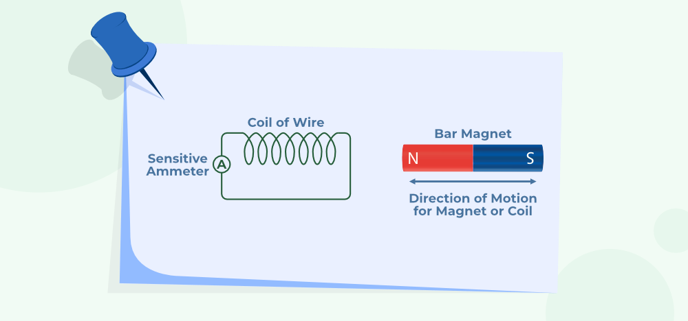
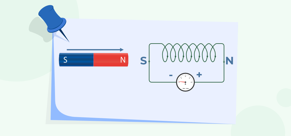
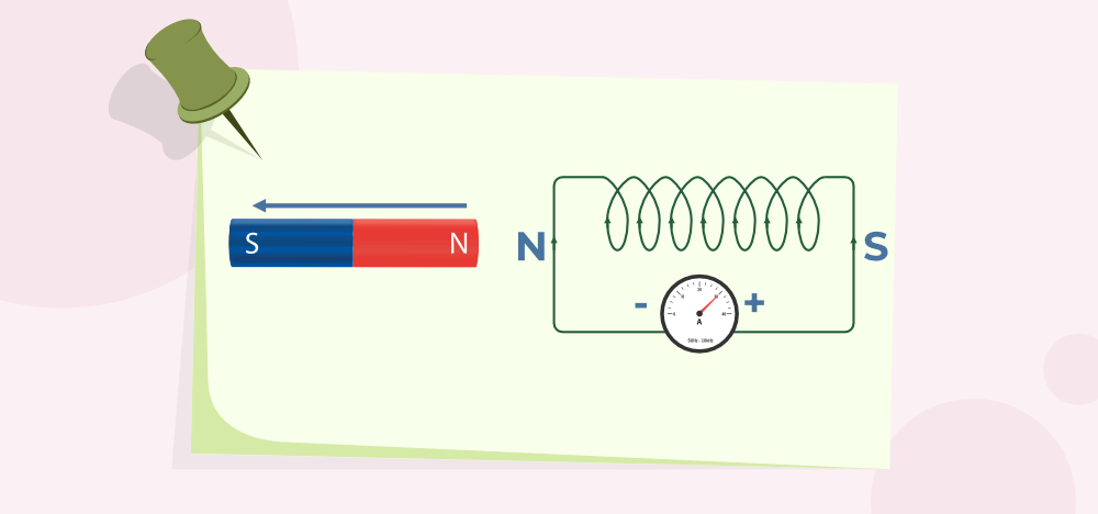
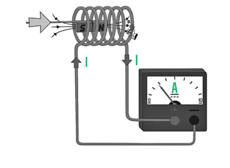
A coil C is connected to a galvanometer G in the diagram below. When the North pole of a bar magnet is pushed towards the coil, the galvanometer’s pointer deflects, indicating the presence of electric current in the coil. The deflection is permanent as long as the bar magnet is moving. When the magnet is not moved that is held stationary, then there is no deflection in the galvanometer. The galvanometer deflects in the opposite direction when the magnet is pushed away from the coil, showing that the current has altered.

Furthermore, when the bar magnet’s South-pole is moved towards or away from the coil, the deflections in the galvanometer are the polar opposite of those seen with the North-pole for similar movements. Furthermore, when the magnet is pushed towards or pulled away from the coil faster, the deflection (and thus current) is found to be greater. Instead, when the bar magnet is held stationary and coil C is moved towards or away from the magnet, the same effects are observed. It demonstrates that the relative motion of the magnet and the coil is responsible for the generation (induction) of electric current in the coil.
Experiment – 2
The bar magnet in the below figure is replaced by a second coil C2 which is connected with a battery. The constant current in coil C2 generates a constant magnetic field. The galvanometer deflects as coil C2 is moved towards coil C1. This indicates that in coil C1, an electric current is being induced. The galvanometer deflects again when C2 has moved away but in the opposite direction. The deflection will last as long as coil C2 is moving. The same effects are observed when coil C2 is held fixed and coil C1 is moved. Again, it is the relative motion of the coils that causes the electric current to flow.

Experiment – 3
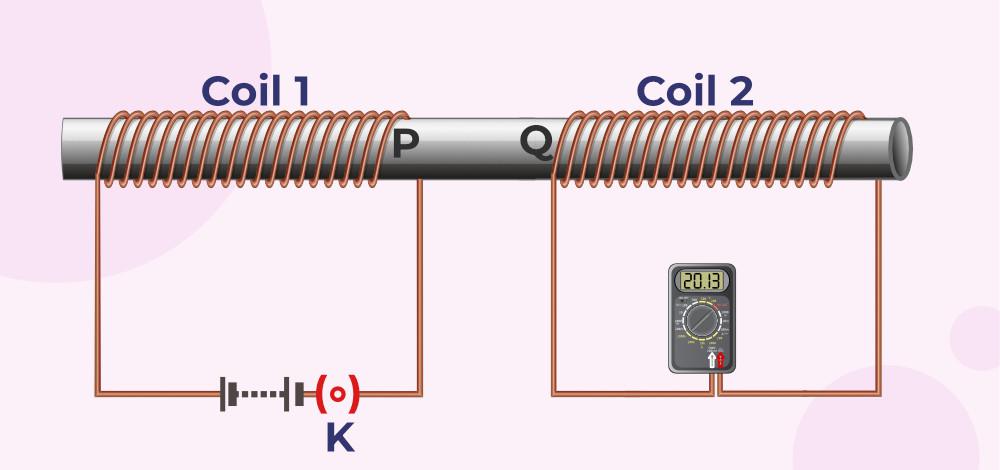
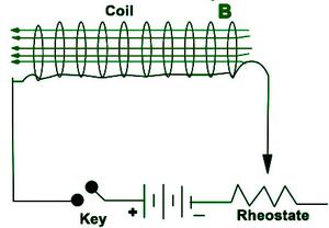
The previous two experiments involved relative motion between a magnet and a coil, as well as between two coils. Faraday demonstrated in another experiment that relative motion is not an absolute requirement. The figure depicts two coils, C1 and C2, that are held stationary. Coil C1 is connected to the G is galvanometer and coil C2 is connected with the battery along with a tapping key K.

When the tapping key K is pressed, the galvanometer exhibits a momentary deflection. The galvanometer’s pointer immediately returns to zero. There is no deflection in the galvanometer if the key is held down continuously. When the key is released, a brief deflection is observed, but this time in the opposite direction. When an iron rod is inserted into the coils along their axis, the deflection increases dramatically.
Sample Questions
Question 1: What would you do to get a large galvanometer deflection?
Answer:
One or more of the following steps can be taken to obtain a large deflection-
- Insert a soft iron rod into the coil C2,
- We can connect powerful battery in coil, and
- By moving faster the arrangement towards the test coil C1.
Question 2: In the absence of a galvanometer, how would you demonstrate the presence of an induced current?
Answer:
Replace the galvanometer with a small bulb, and the relative motion of the two coils will cause the bulb to glow, indicating the presence of an induced current.
Question 3: In experiment 3 what happens when the tapping key is pressed?
Answer:
The galvanometer exhibits a momentary deflection and immediately returns to zero.
Question 4: What happens when a magnet is rapidly brought close to a coil?
Answer:
The induced current in the coil will be greater because the number of magnetic fields passing through the coil will change more rapidly, resulting in a greater induced current.
Question 5: What happens if a coil and a magnet move in the same direction and same speed?
Answer:
When the coil and a magnet are moved in the same direction and at the same speed, the magnetic field across the coil does not change, and thus no electric current is induced in the coil.
Magnetic Flux
Magnetic Flux is defined as the surface integral of the normal component of the Magnetic Field(B) propagating through that surface. It is indicated by φ or φB. Its SI unit is Weber(Wb). The study of Magnetic Flux is done in Electromagnetism which is a branch of physics that deals with the relation between Electric Current and Magnetic Field.
Table of Content
In this article, we will learn about Magnetic Flux in detail and also learn about laws related to it.
What is Magnetic Flux?
Magnetic flux is the measure of the total magnetic field that penetrates a specified closed surface, quantified by counting the magnetic field lines that intersect it. This concept applies to surfaces of any size and orientation relative to the magnetic field’s direction.
Magnetic Flux Definition
Magnetic Flux is defined as,
The number of Magnetic Field lines flowing through a closed surface is known as Magnetic Flux. It calculates the total magnetic field that travels across a specific surface area.
The region under consideration might be any size and can be oriented in any direction about the magnetic field direction.
Magnetic Flux Symbol
The Greek letter Phi or the Phi suffix B is often used to represent Magnetic Flux. The symbol for Magnetic Flux is ϕ or ϕB.
Magnetic Flux Formula
Magnetic Flux Formula is given as:
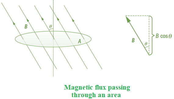
ϕB = B.A = B A cosθ
where
- A is the Surface Area
- B is the Magnetic Field
- θ is the Angle at which lines pass through the Area
- ϕB is the Magnetic Flux
Understanding Magnetic Flux
The development of the concept of Magnetic Flux is attributed to Michael Faraday. Faraday’s breakthrough came when he discovered a simple mathematical relationship to explain a series of electromagnetic induction tests he did. Faraday is largely regarded as the greatest experimental scientist of the nineteenth century, having made significant advances to science. Before we begin to appreciate his work, we must first comprehend the idea of magnetic flux, which is critical to electromagnetic induction.
We use the Field-Line picture of a Magnet or a set of magnets to compute the Magnetic Flux. The scalar product of the magnetic field and area ‘A’ gives the Magnetic Flux through a plane of area ‘A’ that is put in a Uniform Magnetic Field of magnitude B. It’s also necessary to consider the angle at which the field lines travel across the given surface area.
Mathematically,
ϕB = B.A = B A cosθ
where, θ is the angle between vectors A and B.
The resultant flux depends on the glancing angle in the following manner:
- When the angle is 90°, the flux is lowest as Cos 90° is zero.
- When the angle is 0°, the flux is largest as Cos 0° is 1.
Calculation of Total Magnetic Flux
If the Magnetic Field is non-uniform, with various magnitudes and directions at different areas of the surface, the total magnetic flux across the surface may be calculated as the product of all such area elements and their respective magnetic fields.
Mathematically,
ϕB = B1.dA1 + B2.dA2 + B3.dA3 + … = ∑all Bi.dAi
Magnetic Flux is Vetor or Scalar
The Magnetic Flux is a Scalar quantity, as shown by the equation above. Weber (Wb) or Tesla Meter Squared is its SI unit (Tm2).
Measurement of Magnetic Flux
A Magnetometer may be used to measure the Magnetic Flux. Assume a magnetometer probe is moved over a 0.9 m2 region near a huge sheet of magnetic material and shows a constant reading of 10 mT. The magnetic flux through that area is then computed using the formula (10 × 10−3 T) (0.9 m2) = 0.0090 Wb. It would be essential to find the average measurement in the event of shifting magnetic field readings across a large region. The Weber (Wb) or Tesla Meter Squared (Tm2) unit of Magnetic Flux is named after German scientist Wilhelm Weber.
Magnetic Flux Unit
A Flux Meter is used to measure the Magnetic Flux. The following are the SI and CGS units of Magnetic Flux:
- Weber (Wb) is the SI unit for Magnetic Flux.
- Volt-Seconds is the fundamental unit of Magnetic Flux
- Maxwell is the CGS unit of Magnetic Flux
Gauss Law of Magnetism
Gauss’s Law of Magnetism states that the net magnetic flux through any closed surface is zero. Let’s say Magnetic Flux through an elemental area ΔA is given by ΔφB = B. ΔA then net Magnetic Flux is given as
φB = ∫ΔφB = ∫B. ΔA = 0
It means that the total number of magnetic field lines entering the surface is equal to the total number of lines exiting the surface.
Physical Significance of Gauss Law of Magnetism
The physical significance of Gauss law is that there is no source or sink of magnetic field lines, and isolated magnetic monopoles don’t exist i.e. even the smallest magnetic element consists of a dipole or a current loop.
What is Magnetic Flux Density?
The force operating per unit current per unit length on a wire positioned perpendicular to the magnetic field is called Magnetic Flux Density(B). In simple terms, it is the Magnetic Flux per unit area positioned perpendicular to the Magnetic Flux. Magnetic Flux Density is a Vector Quantity. It is represented by B.
Magnetic Flux Density Formula
Magnetic Flux Density Formula is given as:
B = F ⁄ I L
where,
- I is the current flowing through the wire
- L is the length of wire
- F is the total force acting on the wire
Magnetic Flux Density Unit
The Unit of Magnetic Flux Density is
- Tesla (T) or Kg s−2 A−1 is the SI unit of Magnetic Flux Density
- Gauss is the CGS Unit of Magnetic Flux Density
Read More,
Magnetic Flux
What is Magnetic Flux?
Magnetic Flux is defined as the number of Magnetic Field lines passing through a closed surface. It is the surface integral of the normal component of the Magnetic Field propagating through that surface.
What is Magnetic Field?
Magnetic Field is the region around a magnet in which it exerts force on another magnetic object. The strength of magnetic field decreases as we go away from the magnet.
How is Magnetic Field Produced?
When a charged particle move it produces magnetic field around it.
What is the Formula for Magnetic Field Density?
Formula of Magnetic Field Density is given by B = F ⁄ I L.
What is the Basic Source of the Magnetic Field?
A moving electric charge is the basic source of the Magnetic Field.
Why Magnetic Field lines are Closed Curves?
Since, as per Gauss Law of Magnetism, Magnetic MonoPole doesn’t exist hence magnetic field lines originate from one pole and enter other making closed curves.
Why Magnetic Field Lines never intersect?
The direction of the Magnetic Field at a point is given by tangent to the Magnetic Field lines. If they intersect then there will be two tangents indicating two directions which is not possible hence Magnetic filed lines never intersect.
Faraday’s Laws of Electromagnetic Induction
Faraday’s Law of Electromagnetic Induction is the basic law of electromagnetism that is used to explain the working of various equipment that includes an electric motor, electric generator, etc. Faraday’s law was given by an English scientist Michael Faraday in 1831. According to Faraday’s Law of Electromagnetic Induction, the induced current in the circuit is directly proportional to the rate of change of Magnetic Flux.
Let’s learn about Faraday’s Law of Electromagnetic Induction, its experiment, derivation, examples, and others in detail in this article.
Faraday’s Law Definition
The basic law of electromagnetic induction predicting how a magnetic field interacts with an electric circuit to produce the electromotive force (EMF) is called Faraday’s Law. And this phenomenon of producing the electromotive force in the electric circuit by the interaction of the magnetic field is called Electromagnetic Induction.
Faraday’s Laws of Electromagnetic Induction
Faraday has provided two laws that are the basis of modern electromagnetism. The laws are discussed below:
- Faraday’s First Law of Electromagnetic Induction
- Faraday’s Second Law of Electromagnetic Induction
Faraday’s First Law of Electromagnetic Induction
According to Faraday’s First Law of Electromagnetic Induction, “When the Magnetic Flux linked with closed-circuit changes, an EMF is induced in it which lasts only as long as the change in flux is taking place. If the circuit is closed then current also gets induced inside the circuit which is called ‘Induced current”. Changing the magnetic field changes the induced current in the circuit.
The image given below shows the deflection in the coil according to the law of Electromagnetic Induction.
Magnetic Fields Can be changed by,
- Moving a bar magnet towards or away from the coil.
- Moving the coil into the magnetic field or outside the magnetic field.
- Rotating the coil relative to the magnet.
- Changing the area of a coil placed in the magnetic field.
Faraday’s Second Law of Electromagnetic Induction
According to Faraday’s Second Law of Electromagnetic Induction, “The magnitude of the induced emf is equal to the rate of change of magnetic flux linked with the coil.”
E = dⲫ/dt
E = -N dⲫ/dt
E = -N (ⲫ2-ⲫ1)/t
where,
E is Electromotive Force
N is the Number of turns of the coil.
ⲫ is the Flux Change
Lenz’s Law Definition
Lenz’s Law is named after the German physicist “Emil Lenz “, who formulated it in 1834. According to Lenz Law, “the direction of induced current in a circuit is such that it opposes the change in magnetic flux produced.” It is a scientific law that specifies the direction of induced current but states nothing about its magnitude.
According to Faraday’s Second Law of Electromagnetic Induction,
E = -N(d∅/dt)
Here, the negative sign indicates that the direction of induced emf is such that it opposes the change in magnetic flux which is in accordance with Lenz’s law
Faraday’s Experiments
Faraday has performed three experiments that form the basis of electromagnetic induction.
Experiment 1
In this experiment, Faraday took a circular coil and connected it with a galvanometer and now he takes a strong bar magnet. When the north pole of the bar magnet is moved towards the coil, the galvanometer showed deflection to the right side of the zero mark in the galvanometer. When the magnet is moved away from the coil again it showed deflection but in the opposite direction. Similarly, the experiment is done with the south pole of the bar magnet, again the deflection is observed but opposite to the direction shown by the north pole of the bar magnet. When the magnet is held stationary near the coil, no deflection is observed in the galvanometer.
Conclusion: As the magnet is moved closer to the coil the magnetic flux increases hence, an induced current setup in the coil in one direction. When the magnet is moved away from the coil, the magnetic flux decreases, hence an induced current set up in the coil in the opposite direction. When the magnet is held stationary near the coil, there is no change in the magnetic flux.
Experiment 2
In this experiment, the bar magnet is kept stationary and the coil is moved. The same result is observed in experiment 1. When the relative motion between the magnet and coil is fast, the deflection in the galvanometer is larger and vice versa.
Experiment 3
As you can see from the figure below. Two coils primary (p) and secondary (s), are wound on cylindrical support. The primary coil is connected to a key, a rheostat, and a battery. The secondary is connected with a galvanometer. When the key is pressed in the primary coil the galvanometer shows deflection in one direction. When the key is released, it again shows deflection but in the opposite direction. When the key is kept pressed steady current flows through the primary coils, and the galvanometer does not show any deflection. When the current in the primary coil is increased with the help of the rheostat, the induced current flows in the secondary coil in the same direction as that of the primary coil.
The image given below shows the setup of Faraday’s Experiment.
All three Faraday Experiments can be summarised in the table given below,
Position of Magnet | Deflection in Galvanometer |
|---|---|
| When the magnet is at Rest | No deflection is observed in the Galvanometer |
| When the magnet moves toward the coil | Deflection is observed in the galvanometer in one direction. (say clockwise) |
| When the magnet moves away from the coil | Deflection is observed in the galvanometer but in the opposite direction. (say counter-clockwise) |
| When the magnet is held stationary at the same position (near the coil) | No deflection is observed in the Galvanometer |
| When the magnet is held stationary at the same position (away from the coil) | No deflection is observed in the Galvanometer |
Faraday Law Formula
Faraday Law formula can be easily calculated as suppose we take a bar magnet approaching a coil and we measure the flux associated with the coil at two-time instances T1 and T2. The change in flux results in the production of EMF which causes electrons to move to constitute current.
The image given below tells us about the change in electromagnetic force linked with the coil when the magnet moved close to the coil.
At T1, the flux associated with the coil = Nϕ1
At T2, the flux associated with the coil = Nϕ2
Change in flux = N(ϕ1 – ϕ2) = Nϕ
Rate of change of flux = Nϕ/t
Taking the derivative, and equating it with E(electromotive force), according to Faraday’s law of electromagnetic induction, the rate of change of flux is equal to induced emf.
E = Ndϕ/dt
Considering Lenz’s Law the emf opposes the cause which produces it,
E = -Ndϕ/dt
where,
E is the electromotive force
Φ is the flux measured in the coil
N is the number of turns in the coil
Faraday’s Law Derivation
The derivation of Faraday’s Law is explained below:
Now we take a magnet approaching a coil and consider instances at times T1 and T2
At time T1 flux linked with the coil = NΦ1
At time T2 flux linked with the coil = NΦ2
Change in flux = N(Φ2 – Φ1)
Rate of change of flux = N(Φ2 – Φ1) / t
Taking the derivative of the above equation, we get
Derivative of Rate of Change of Flux = N dΦ/dt
Faraday’s second law of electromagnetic induction, says that the induced emf in a coil is equal to the rate of change of flux associated with the coil. Thus,
E = – N dΦ/dt…(1)
The negative sign is added as it helps to accommodate Lenz’s law.
Change in Electromagnetic Force
Electromagnetic Force linked with the coil can easily be changed by following the steps discussed below.
- Induced EMF can easily be increased by increasing the number of turns in the coil.
- If the magnetic field strength increases induced EMF also increases
Applications of Faraday’s Law
Faraday’s law has various applications and some of the common applications of Faraday’s Law are,
- Faraday’s Law is used in electrical equipment like transformers and electric motors.
- Induction cooker works on the principle of mutual induction, which is derived from Faraday’s law.
- Faraday’s law is also helpful in designing musical instruments like the electric guitar, electric violin, and others.
How To Increase EMF Induced in a Coil
The emf of the coil can be increased by following the steps discussed below,
- By Increasing the Number of Turns in the Coil.
- By Increasing Magnetic Field Strength.
- By Increasing the Speed of the Relative Motion between Coil and Magnet.
Thus, the steps discussed above increase the induced emf induced in a coil.
Read More
Solved Examples on Faraday’s Law of Electromagnetic Induction
Example 1: The magnetic flux linked with a coil is changed from 2Wb to 0.2Wb in 0.5 seconds. Calculate the induced emf.
Solution:
Δⲫ = 0.2-2 = 1.8wb
Δt = 0.5 sec
E = -(Δⲫ/Δt)
E= -1.8/0.5 volts
E= -3.6 volts
Therefore, induced emf will be -3.6 volts.
Example 2: In a coil of resistance 200, a current is induced by changing the magnetic flux through it as shown in the figure. Calculate the magnitude of change in flux through the coil.
Solution:
dq = – (N/R) dt
i = (1/R). (dq/dt)
Δⲫ = R.Δq
Δⲫ = 200 × (Area of circular graph)
Δⲫ = 200 × (1/2×20×0.5)
Δⲫ = 200 × 5
Δⲫ = 1000 Wb
Therefore, magnitude of change in flux is 1000 Wb.
Example 3: Calculate the emf induced in the wire. When a small piece of metal wire dragged across the gap between the pole pieces of a magnet in 0.6sec. The magnetic flux between the pole pieces is known to be 9×10⁻⁴ Wb.
Solution:
dt = 0.5 s
dⲫ = 9×10⁻⁴-0 = 9×10⁻⁴ Wb
E = (dⲫ)/dt
E= (9×10⁻⁴)/0.6
E= 0.0036 V
Therefore, the induced emf 0.0036V
FAQs on Faraday’s Law of Electromagnetic Induction
Q1: What is Faraday’s Law of Electromagnetic Induction?
Answer:
There are two laws explained by Faraday called Faraday’s Laws of Electromagnetic Induction. First law explains the induction of emf in a conductor and the second law tells the emf produced in the conductor.
Q2: What is Faraday’s First Law of Electromagnetic Induction?
Answer:
Faraday’s first law of Electromagnetic Induction states that, “ An EMF is produced when a conductor is placed in a varying magnetic field”, and the current produced in this process is called Induced Current.
Q3: What is Faraday’s Second Law of Electromagnetic Induction?
Answer:
Faraday’s second law of Electromagnetic Induction states that, “ The rate of change of flux is directly proportional to the induced current in a coil.”
Q4: Why are Faraday’s Laws important?
Answer:
Faraday’s law is used to define the EMF produce inside a coil if it rotates in a magnetic field. This concept is widely used in modern-day physics.
- It is used in electric motors.
- It is used in electric generators.
Q5: What is meant by EMF?
Answer:
EMF also called Electromotive Force is the energy required to flow the current in the circuit.
Q6: What is Faraday’s Formula?
Answer:
The Faraday law formula is,
E = -Ndϕ/dt
where,
E is the electromotive force
Φ is the flux measured in the coil
N is the number of turns in the coil
Q7: What are the Applications of Faraday’s law?
Answer:
Various applications of the Faraday laws are,
- It used to explain the working Electric Transformer and Electric Motor
- It explains the forces acting on the electric circuit by the electromagnetic field.
Lenz’s Law
Lenz law was given by the German scientist Emil Lenz in 1834 this law is based on the principle of conservation of energy and is in accordance with Newton’s third law. Lenz law is used to give the direction of induced current in the circuit.
In this article, let’s learn about Lenz law its formula, experiments, and others.
What is Lenz’s law?
The general definition of Lenz’s Law is,
“The induced current in a circuit due to Electromagnetic Induction always opposes the change in magnetic flux.”
It is a scientific law that specifies the direction of induced current but states nothing about its magnitude. The magnetic field associated with the closed circuit amplifies the induced current flow in such a way that it creates a magnetic field in the opposite direction of the original magnetic field. Thus, opposing the cause which produced it and stating its similarity with Newton’s third law.
Lenz’s Law Formula
Lenz’s Law formula is stated from Faraday’s Law of Electromagnetic Induction. According to this law, EMF on the coil is calculated as,
E = -N(d∅/dt)
where,
negative sign indicates that the direction of induced emf is such that it opposes the change in magnetic flux)
E is the electromotive force
N is number of loops the coil made
d∅ is the change in magnetic flux
dt is change in time
Lenz’s Law Experiment
Lenz’s law provides the direction of the induced electromotive force and current induced in the closed circuit. The experiments proved by Lenz to state its theory are,
The image given below shows a metallic conductor placed in a magnetic field.
First Experiment
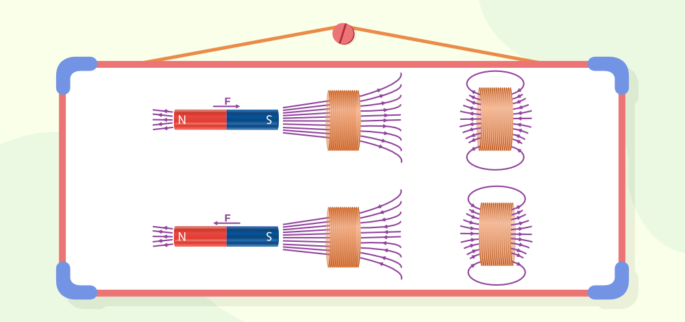
First experiment by Lenz proved that the current flowing in the coil produces a magnetic field in the circuit and the strength of the magnetic field increases with an increase in the strength of the induced current. Also, this magnetic field produced opposes the original magnetic field i.e. the direction of the induced current is opposite to the original magnetic field.
Second Experiment
Second experiment by Lenz states that the iron rod wound by the current-carrying wire and its left end behave as N-pole if moves towards the coil an induced current is produced in the coil.
Third Experiment
Third experiment by Lenz states that if the coil is pulled towards the magnetic flux, the magnetic flux linked with the coil decreases as the area of the coil inside the magnetic field decreases. Now the induced current in the same direction opposes the motion of the coil according to Lenz’s law.
From the above experiments, we can conclude that the current is produced when the magnet exerts the force in the loop and to resist the change, the current exerts a force on the magnet.
What is Electromagnetic Induction?
It is the phenomenon of production of induced emf due to a change of magnetic flux (number of magnetic field lines) connected to a closed circuit called electromagnetic induction.
Lenz’s Law Explanation
Lenz’s law is easily explained by two cases.
Case 1:
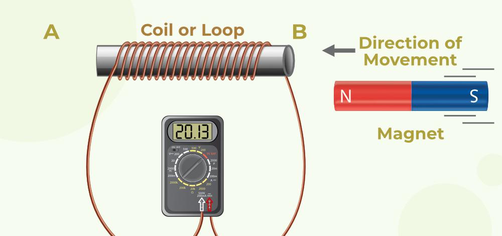
As shown in the figure, when the North pole bar magnet is moved towards the coil, the induced current in the coil flows in the anticlockwise direction, when we see it from the magnet side. The face of the coil develops north polarity. As we know, that same pole repels, so the north pole-north pole repels. So, it opposes the motion of the North pole of a magnet.
Conclusion: The motion of the magnet increases the flux through the coil and flux will be generated in the opposite direction by the induced current.
Case 2:
As shown in the figure when the North pole of a bar magnet is taken away from the coil, the induced current in the coil flows in the clockwise direction. The face of the coil develops South polarity. We know that opposite poles attract. So, the north pole and south polarity attract each other.
Conclusion: The motion of the magnet decreases the flux through the coil. The flux is generated in the same direction by induced current, hence opposing and increasing the flux.
Lenz’s Law Applications
Lenz’s Law finds its importance in various cases and some of the most common uses of Lenz’s law are,
- The braking system in trains works on the principle of Lenz’s law
- AC generators work on the principle of Lenz’s law
- Eddy currents are balanced using Lenz’s Law
- Metal Detectors, Card readers, and many other electronic devices use the concept of Lenz’s law for their application.
Lenz’s law and Law of Conservation of Energy
Lenz’s law is a consequence of the law of conservation of energy. The law of conservation of energy states that energy can neither be created nor be destroyed, but it can be changed from one form to another form. Lenz’s law states that the direction of current is such that it opposes the change in the magnetic flux. So, extra effort is required to do work against opposing forces. This extra work leads to periodic changes in magnetic flux hence more current is induced. Thus, the extra effort gets converted into electrical energy only, which is nothing but the law of conservation of energy.
The magnetic flux increases as the North Pole of the magnet approaches it and drops as it is driven away in the activity above. In the first scenario, opposing the cause involves moving the magnet, and the face facing the coil gains North Polarity. The magnet’s north pole and the coil’s north pole repel each other. To counteract the force of repulsion, mechanical action must be done to bring the magnet towards the coil. This mechanical energy is transformed into electrical energy. Due to Joule’s Effect, this electrical energy is turned into heat energy.
The image given below shows the magnetic flux linked with the coil when a magnet is taken close or away from the coil.
When the magnet is moved away from the coil, the coil’s nearer face obtains south polarity. In this instance, the produced emf will oppose the magnet’s outward motion. To resist the force of attraction between the North Pole of the magnet and the South Pole of the coil, mechanical labour must be done once more. This labour is transformed into electrical energy.
There is no mechanical work done if the magnet is not moved, hence no emf is induced in the coil.
As a result, Lenz’s Law is consistent with the law of conservation of energy.
Also, Check
FAQs on Lenz’s Law
Q1: What is Lenz’s law?
Answer:
Lenz’s law states that the Induced current in a coil is in that direction which opposes the change in magnetic flux through the coil.
Q2: Where is Lenz’s law used?
Answer:
Lenz’s law is used to find the direction of induced current in any circuit. It works in accordance with Newton’s third law.
Q3: What is the difference between Lenz’s law and Faraday’s law?
Answer:
The difference between Faraday’s law and Lenz’s law can be explained through,
Lenz’s law states the direction of an induced current.
Faraday’s law states that the magnitude of the emf induced in a circuit is proportional to the rate of change of magnetic flux.
Q4: What is the History of Lenz law?
Answer:
A Baltic German physicist Heinrich Lenz proposed the Lenz Law in early 1900s
Q5: Which law gives the direction of current in an AC generator?
Answer:
Lenz’s law is used to provide the direction of current in an AC generator.
Q6: How is Lenz’s law related to the law of conservation of energy?
Answer:
Lenz’s law states that the induced EMF in the coil always opposes the cause which produces it which is in accordance with the law of conservation of energy.
Q7: What does the negative sign indicate in Lenz’s law?
Answer:
The negative sign in Lenz’s law indicates that “the induced emf produced in the coil due to electromagnetic induction is opposite to the cause which creates the current in the coil.”
Q8: Which principle of conservation derives the Lenz Law?
Answer:
Lenz law is derived from the law of conservation of energy.
Motional Electromotive Force
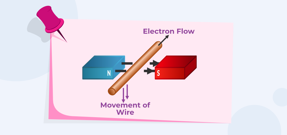
The process of induction occurs when a change in magnetic flux causes an emf to oppose that change. One of the main reasons for the induction process in motion. We can say, for example, that a magnet moving toward a coil generates an emf, and that a coil moving toward a magnet creates a comparable emf.
This section will cover motion in a magnetic field that is stationary in relation to the planet Earth, resulting in motional emf. The Hall effect is one scenario where we may claim there is a motion that typically happens. The magnetic force experienced by moving charges in a magnetic field is indicated by
F = qvB sinθ
where F is the magnetic force, q is the charge, v is the velocity and B is the magnetic field.
What is Lenz’s law?
Lenz’s law states that “The direction of the induced current is such that it opposes the change that has induced it.” i.e. when the magnetic flux through closed-loop changes, an electric current results in a direction so that it opposes the change that has induced it.
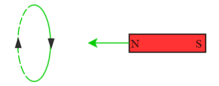
As the magnet gets closer to the loop, the number of magnetic field lines passing through the area increases thus leading to an increase in the magnetic flux. So according to the law, the induced current should weaken the flux. The field of the bar magnet is away from the magnet, so the induced field should be towards the magnet. Using the right-hand thumb rule, we find the direction of the current that produces a field towards a magnet i.e. north pole of the bar magnet faces the north pole of the loop. This is why we feel a slight force against the motion.
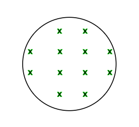
Example 1: In the given figure, the number of field lines passing through the loop increases. Find the direction of the induced current.
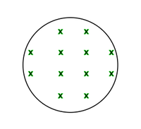
Answer:
We know that, the magnetic flux is:
φ = B . A
= B A cosθ, (here θ = 0o)
where B is the magnetic field and A is the area of cross-section.
According to Lenz’s law, the direction of induced current should be in such a way that it opposes the change that induced it.
Here the change is increased in magnetic field . so in order to counter this, the induced magnetic field should be out of the plane. Using right-hand thumb rule, we get, The direction of induced current should be counter-clockwise/anti-clockwise direction.
Example 2: Consider the following figure where a conducting loop is placed near a long, straight wire carrying i. If the current increases continuously, find the direction of the induced current in the loop.
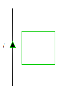
Answer:
Using right-hand thumb rule, we get the direction of the magnetic field produced due to the current-carrying wire being perpendicular to the loop and is going into the plane. Since the magnitude of the current is continuously increasing, the magnitude of the magnetic field also increases. Thus the flux through the loop increases.
So according to the Lenz’s law, the direction of induced current must be anti-clockwise to counter the change in the magnetic field.
Faraday’s Law of Electromagnetic Induction
Faraday after performing a number of experiments discovered the following law in nature: Whenever the flux of magnetic field through the area bounded by a closed conducting loop changes, an emf is produced in the loop.
The emf is given by,
ε = – dφ/dT
where φ =∫B . dS is the flux of the magnetic field through the area.
The SI unit of magnetic flux is called Weber which is equivalent to the Tesla meter. The -ve sign shows the direction of the induced current which we can find using Lenz’s law. The flux can be changed in a number of ways-
- By change in the magnitude of magnetic field B at the site of the loop.
- By change in the area of the loop
- By change in the angle between the area vector A and the field B.
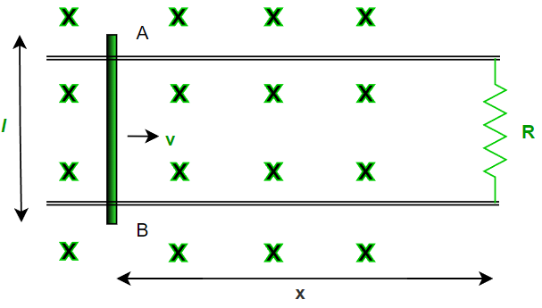
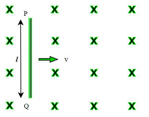
Let us try to understand this through an experiment. A conducting rod AB of length l is moving on a rail with negligible resistance with velocity v in the uniform magnetic field B perpendicular to the plane of motion. We need to find out the current passing through the resistance R.
Let x be the distance between the resistance and the rod at any timer t . According to faraday’s law, emf produced in a loop due to change in magnetic flux is,
ε = – dφ/dT
φt (flux at any time t) = B . A
= B l x
⇒ d (φt )/dt = d (Blx)/dt
= Bl dx/dt
= Blv (since B and l are constants)
Therefore,
ε = – dφ/dT
= Blv
Using Ohm’s law: V = IR or I = V/R
Current through the resistance R is,
I = Blv/R (in a clockwise direction)
Amount of charge (q) passed through the loop in time ‘t’ = Δφ/R
where Δφ = Total change in flux in time ‘t’.
Example 1: The magnetic field into the plane of the loop is B(t) = 2t2. The cross-sectional area of the loop is 3 m2. Calculate the emf in the loop at time t = 3 seconds.
Answer:
Magnetic flux at any time t is , φ = B.A = 2t2.3 = 6t2 .
ε = – dφ/dT
= d(6t2)/dt
= 12t
EMF at t = 3sec ,
ε = 12(3)
= 36 volts.
Example 2: Considering the resistance of the loop to be 2 ohms, find the charge passed through the loop with reference to previous example.
Answer:
Here, φ, at t = 0 = 2(0)=0.
And, φ, at t = 3 sec , = 2(3)2 = 18 .
Amount of charge (q) passed through the loop in time ‘t’ = Δφ/R = 18/2 = 9 Coulombs.
Motional EMF
So what exactly is the external mechanism that maintains the electric field in the loop to drive the current? or, what is the mechanism to produce an emf? Let’s dive into this.
The magnetic flux φ =∫B . dS can be changed by –
- Keeping the magnetic field constant as time passes and moving the whole part of the loop.
- Keeping the loop at rest and changing the magnetic field.
- Combination of both (1.) and (2.).
Fig.1 shows a rod PQ if length l moving in a magnetic field B with a constant velocity v. The length of the rod is perpendicular to the magnetic field and the velocity is perpendicular to both the magnetic field and the length of the rod.
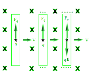
At t=0 s, the free electrons of the wire also move with this velocity v together with the random velocity they have in the rod. As we know that the magnetic force due to the random velocity is zero on average. Thus the magnetic field exerts an average force of:
Fb = q(v x B)
where the charge on q is assumed as + 1.6 x 10⁻¹⁹. If we consider q as an electron, the magnitude of force remains the same but the direction reverses due to the negative charge in the electron.
This force is towards PQ and hence the electrons will move towards P. At time say t= ‘t’s, some amount of negative charge is accumulated at P and the positive charge appears at Q. So as a result of the accumulation of opposite charges at the endpoint, an electrostatic field E is developed within the wire from Q to P. The field exerts a force Fe = qE on each charge q.
The charge keeps on accumulating until a situation comes when Fb = Fe. Suppose at time t= T s, the equilibrium is achieved.
That means |q(v x B)| = |qE|
or
vB = E
After this, there is no resultant force on the free electrons of the wire PQ. The potential difference between the ends Q and P is,
V = El = vBl
Thus, it is the magnetic force on the moving free electrons that maintains the potential difference V = vBl and hence produces an emf ∈ = vBl. As this emf is produced due to the motion of a conductor, it is called motional emf.
or more precisely,
∈ = (v x B) . l
i.e. the dot product of the length of rod l with the cross product of velocity v and magnetic field B. Using faraday’s law, we get the same result.
Sample Problems
for reference purposes
Problem 1: A rod PQ of length 10 m is moving with velocity 10 m/s in x axis under the influence of magnetic field of magnitude 8 T as shown in the fig. . Calculate the emf generated across its length after equilibrium is attained.
Answer:
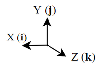
We know that , v =–10 i , B = 8 k and l = 10 j. Since emf ∈ = (v x B) . l
So we will first find cross product of v and B.
(v x B) = (-10 i) x (8 k) = 80 j , since i x k = -j
this implies that end P is of higher potential & Q is of lower potential as force on an electron will be downwards i.e. -j as F =q(v x B).
EMF ∈ = (v x B) . l = (80 j) . (10 j) = 800 V. since j . j = 1
Therefore emf generated across the rod PQ is 800 V.
Problem 2: A rod PQ of length 1 m is moving with velocity 5 m/s at an angle of 37o from horizontal under the influence of magnetic field of magnitude 8 T as shown in the fig. . Calculate the emf generated across its length after equilibrium is attained.
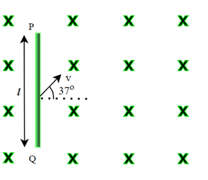
Answer:
We know that , v =(-5cos37oi + 5sin37o j) , B = 8 k and l = 1 j. Since emf ∈ = (v x B) . l
So we will first find cross product of v and B.
v x B = (-5cos37oi + 5sin37o j) × (8k) = (4 j + 3 i) since cos 37 = 4/5 , sin 37 = 3/5 , i x k = -j and j x k = i
this implies that end P is of higher potential & Q is of lower potential as F =q(v x B).
EMF ∈ = (v x B) . l = (4 j + 3 i) . (1 j) = 4 V. since j . j = 1 and i . j = 0
Therefore emf generated across the rod PQ is 4 V.
Problem 3: A rod PQ of length 1 m is moving with velocity 10 m/s horizontally under the influence of magnetic field of magnitude 8 T as shown in the fig. . Calculate the emf generated across its length after equilibrium is attained.
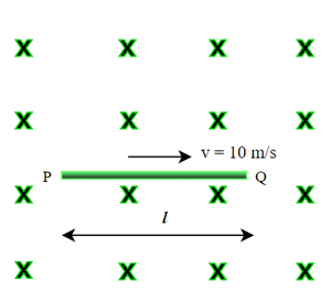
Answer:
We know that v =-10 i , B = 8 k and l =-1 i. Since emf ∈ = (v x B) . l
v x B = -10 i x ( 8 k ) = 80 j
∈ = (v x B) . l = 80 j . (-1 i) = 0
As we can see that the direction of v x B is perpendicular to the length of the rod l , emf generated will be zero.
That implies end P and Q are equipotential.
Problem 4: Consider a conducting rod of length 1 m (l = -1 j) , B = 1 i +2 j+3 k and v = 4 i +5 j+6 k . Calculate the emf generated within the rod.
Answer:
We know that v = 4 i +5 j+6 k , B = 1 i +2 j+3 k and l =-1 j. Since emf ∈ = (v x B) . l
So we will first find cross product of v and B.
(v x B) = (v = 4 i +5 j+6 k) x ( B = 1 i +2 j+3 k ) = 3 i – 6 j +3 k.
EMF ∈ = (v x B) . l = ( 3 i – 6 j +3 k) . (-1 j) = 6V.
Therefore emf generated across the rod is 6 V.
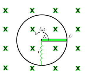
Problem 5: A conducting rod AB of length l is hinged and rotated about end A, perpendicular to the uniform magnetic field B with constant angular velocity ω as shown. Calculate induced emf between two ends of the rod.
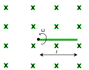
Answer:
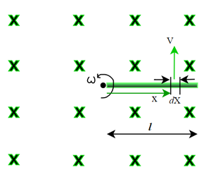
As we move from A to B, the velocity of every other point on the rod is different. So we have to apply method of integration as we cannot apply the formula directly.
Let us consider an element of length dx at a distance x from the end A
Therefore the velocity v of dx element is ωx as shown in fig.
so the emf induced in the element is dE = (v x B) . l = B.ωx.dx . Therefore, we need to integrate dE through the length
∫dE = ∫B.ωx.dx
= B ω 0∫l x . dx
E = 1/2 B ω l2 V .
Therefore emf generated across the rod AB is 1/2 B ω l2 V.
Problem 6: A conducting rod AB of length l = 1m with end A fixed at the center and end B sliding over the circumference of a conducting loop of radius 1 m rotated with constant angular velocity ω = 4 radians/sec. A resistance r = 2 ohms is kept stationary with one end connected to A and other to the loop as shown in the figure. Calculate the current i that flows through the resistance. The magnitude of magnetic field is 2 T.
Answer:
As we have seen in problem no.5 , the emf induced across the ends of a rod moving with angular velocity ω with one of its end fixed is,-
ε = 1/2 B ω l2V.
i.e. ε = 1/2 . 2. 4.1 = 4 V. end A is of higher potential than B
Therefore potential difference across resistance r = 4 V
so using OHM’s law , V = I.R, or I = V/R = 4/2 = 2 A
i.e. current through the resistance r is 2 amperes.
Problem 7: A rod of length l is moving with a velocity v making an angle of 37 degrees with its length. A uniform magnetic field B exists in a direction perpendicular to the plane of the motion. Calculate the induced emf in the rod.
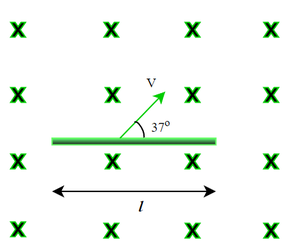
Answer:
We know that emf induced across the end of a rod moving with velocity v is – ∈ = (v x B) . l
i.e. the direction of v x B is 57 degrees clockwise from horizontal.
∈ = vBl cos (90 – 37) = vBl sin 37o = 3 vBl/5 V, since the angle between v x B and l is 53 degrees.
Therefore emf induced across its ends is 3 vBl/5 Volts.
Problem 8: The given figure shows a wire AB of length l = 1m which can slide on a smooth rail of negligible resistance. The resistance of wire r = 1 ohm and external resistance R = 3 ohms. The wire is pulled to the right with constant speed v = 2 m/s. Calculate the amount of current flows through the wire. The magnitude of magnetic field is 2 T.
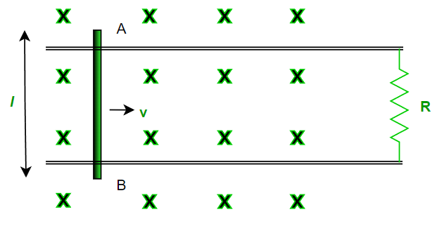
Answer:
METHOD -1
Emf induced across the end of a rod moving with velocity v is – ∈ = (v x B).l
i.e. ∈ = 2. 2. 1 = 4 V.
Equivalent circuit diagram will be –
Using ohm’s law , I = 4/(R+r) = 4/4 = 1 A.
Therefore current through the wire is 1 amperes.
METHOD -2 (Using Faraday’s law)
According to faraday’s law, emf produced in a loop due to change in magnetic flux is,
ε = – dφ/dT = Blv = 2.1.2 = 4 volts
thus , I = V/R = 4/4 = 1 ampere.
Inductance – Definition, Derivation, Types, Examples
Magnetism has a mystical quality about it. Its capacity to change metals like iron, cobalt, and nickel when touched piques children’s interest. Repulsion and attraction between the magnetic poles by observing the shape of the magnetic field created by the iron filling surrounding the bar magnet will be learned.
According to physicists, the forces that govern both magnetism and electricity are substantially greater than gravity in electromagnetism.
What is Inductance?
Inductance is an electrical circuit attribute that opposes any change in current in the circuit. Electrical circuits have an intrinsic feature called inductance. Whether desired or not, it will always be found in an electrical circuit. The inductance of a straight wire carrying electricity with no iron element in the circuit will be lower. Because the inductance of an electrical circuit opposes any change in current in the circuit, it is equivalent to inertia in mechanics.
Magnetic flux that is proportional to the rate of change of the magnetic field is known as induction. The induced EMF across a coil is related to the rate at which the current through it changes. Inductance is the proportionality constant in that relationship. H is the SI unit for inductance (henry). It is denoted by the letter L. The amount of inductance required to produce an EMF of 1 (V) volt in a coil when the current change rate is 1 Henry is defined as 1 H (Henry).
Factors affecting Inductance
The following are some of the factors that influence inductance:
- The inductor’s wire has a specific number of turns.
- The material that was used to make the core.
- The core’s appearance.
Faraday established the Electromagnetic Induction Law, which states that by altering the magnetic flux, an electromotive force is induced in the circuit. The concept of induction is derived from Faraday’s law of electromagnetic induction. The electromotive force generated to counteract a change in current at a specific time interval is known as inductance.
Derivation of Inductance
Take a look at a DC source that has the switch turned on. When the switch is turned on, the current flows from zero to a specific value, causing a change in the flow rate. Consider the flux shift caused by current flow. The flux change is measured in terms of time, as follows:
dφ/dt
Use Faraday’s law of electromagnetic induction to solve the problem.
E = N(dϕ/dt)
Where, N is the coil’s number of turns, and E is the induced EMF across the coil.
Write the above equation as follows using Lenz’s law:
E = -N(dϕ/dt)
For computing the value of inductance, the previous equation is adjusted.
E = -N(dϕ/dt)
∴ E = -L(di/dt)
N = dΦ = L di
NΦ = Li
Therefore,
Li = NΦ = NBA
Where, B denotes the flux density and A denotes the coil area.
Hl = Ni
Where H denotes the magnetic flux’s magnetizing force.
B = μH
Li = NBA
L = NBA/i = N2BA/Ni
N2BA/Hl = N2μHA/Hl
L = μN2A/l = μN2πr2/l
Types of Inductance
There are two types of inductance. They are self-induction and mutual induction. Let’s learn about them in more detail with proper definitions,
Self Induction
The magnetic flux associated with a coil or circuit changes anytime the electric current running through it changes. As a result, an emf is induced in the coil or circuit, which opposes the change that creates it, according to Faraday’s laws of electromagnetic induction. This phenomenon is known as ‘self-induction,’ and the induced emf is referred to as back emf, while the current created in the coil is referred to as induced current.
- Coefficient of self-induction: The current is proportional to the number of flux linkages with the coil, i.e., Nϕ is directly proportional, or Nϕ = Li (N is the number of turns in coil and Nϕ – total flux linkage). Hence The coefficient of self-induction is L = (Nϕ/i).
- If i = 1amp, N = 1 then, L = ϕ i.e. When the current in a coil is 1 amp, the coefficient of self-induction is equal to the flux associated with the coil.
- Faraday’s second law induced emf e = -N(dϕ/dt). Which gives e = -L(di/dt); If di/dt = amp/sec then |e| = L. When the rate of change of current in the coil is unity, the coefficient of self induction is equal to the emf induced in the coil.
- Units and dimensional formula of ‘L’ : It’s S.I. unit, weber/Amp = (Tesla × m2)/ Amp = (N × m)/Amp2 = Joule/Amp2 = (Coulomb × volt)/Amp2 = (volt × sec)/amp = (ohm × sec).
But practical unit is henry (H). It’s dimensional formula [L] = [ML2T-2A-2]
- Dependence of self-inductance (L): ‘L’ is determined by the number of turns (N), the area of cross section (A), and the permeability of the medium, not by the current flowing or changing, but by the number of turns (N), the area of cross-section (A), and the permeability of the medium (μ). ‘L’ does not play a role in the circuit until there is a steady current running through it. Only when there is a change in current does ‘L’ enter the picture.
- The magnetic potential energy of inductor: In order to create a continuous current in the circuit, the source emf must work against the coil’s self-inductance, and any energy expanded for this work is stored in the coil’s magnetic field, which is referred to as magnetic potential energy (U).
U = 1/2 (Li)i = Nϕi/2
The various formulae for L
- Circular coil, L = μ0πN2r/2
- Solenoid, L = μ0N2r/l = μ0n2Al
- Toroid, L = μ0N2r/2
- Square coil, L = 2√2μ0N2a/π
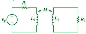
Mutual Induction
When the current going through a coil or circuit varies, so does the magnetic flux coupled to a neighboring coil or circuit. As a result, an emf will be induced in the next coil or circuit. Mutual induction is the term for this occurrence.
- Coefficient of mutual induction: N2ϕ2 is the total flux linked with the secondary due to current in the primary, and N2ϕ2 is directly proportional to i1 = N2ϕ2 = Mi1, where N1 is the number of turns in the primary, N2 is the number of turns in the secondary, ϕ2 is the flux linked with each turn of the secondary, i1 is the current flowing through the primary, and M is the mutual inductance coefficient.
- According to Faraday’s second law emf induces in secondary e2=-N(dϕ2/dt); e2=-M(di1/dt)
- If di1/dt = 1Amp/sec then |e2|=M. When the rate of change of current in the main coil is unity, the mutual induction coefficient is equal to the emf induced in the secondary coil.
- Units and dimensional formula of ‘M’: It’s S.I. unit, weber/Amp = (Tesla × m2)/ Amp = (N × m)/Amp2 = Joule/Amp2 = (Coulomb × volt)/Amp2 = (volt × sec)/amp = (ohm × sec).
But practical unit is henry (H). It’s dimensional formula [M] = [ML2T-2A-2].
- Dependence of mutual inductance:
- Both coils have the same number of turns (N1, N2).
- Both coils’ self-inductance coefficients (L1, L2).
- Coils cross-sectional area.
- The nature of the material on which two coils are coiled or the magnetic permeability of the medium between the coils (μr).
- Two coils are separated by this distance. (As d grows larger, M shrinks.)
- Orientation of main and secondary coils (no flux relation M=0 for 90 degree orientation).
- Between the primary and secondary coils, there is a ‘K’ coupling factor.
- Relation between M, L1, and L2: For two magnetically coupled coils M = K √L1L2, where k – coefficient of coupling or coupling factor which is defined as,
K = Magnetic flux linked in secondary / Magnetic flux linked in primary
0 ≤ K ≤ 1
The various formulae for M
- Two concentric coplanar circular coils, M = πμ0N1N2r2/2R
- Two Solenoids, M = μ0N1N2A/l
- Two concentric coplanar square coils, M = μ02√2N1N2l2/πL
Combination of Inductance
Series
If two mutually inducing self-inductance coils L1 and L2 are connected in series and separated by a large enough distance that mutual induction between them is insignificant, then net self-inductance Ls = L1 + L2.
When they’re near together, the net inductance is Ls = L1 + L2 ± 2M.
Parallel
When two mutually inducting self-inductance coils L1 and L2 are linked in parallel and separated by a large distance, the net inductance L is 1/Lp = 1/L1 + 1/L2.
∴ Lp = L1L2/L1 + L2
When they are in close proximity to one another,
Lp = L1L2 – M2/L1 + L2 ± 2M
Self vs Mutual Inductance
| Self Induction | Mutual Induction |
| The coil’s self-inductance is a property of the coil. | The characteristic of a pair of coils is mutual inductance. |
| When the main current in the coil declines, the induced current resists the decay of current in the coil. | When the main current in the coil declines, the induced current created in the nearby coil opposes the decay of the current in the coil. |
| When the coil’s primary current grows, the induced current opposes the expansion of current in the coil. | When the coil’s primary current grows, the induced current created in the adjoining coil opposes the coil’s current development. |
Things to Keep in Mind
- Magnetic flux that is proportional to the rate of change of the magnetic field is known as induction.
- The induced EMF across a coil is related to the rate at which the current through it changes.
- Inductance is the proportionality constant in that relationship.
- H is the SI unit for inductance (henry). It is denoted by the letter L.
- Faraday’s law of electromagnetic induction is an electromagnetism fundamental law that describes how a magnetic field interacts with an electric circuit to produce an electromotive force (EMF).
- Faraday’s law is the name for this phenomena, which is known as electromagnetic induction.
- Mutual inductance is a property of a pair of conductors, whereas Self Inductance is a property of the conductors individually.
Sample Problems on Inductance
Question 1: Three coils are wired together in a series. Each coil has an inductance of 5H, 4H, and 6H, respectively. Calculate the inductance equivalent.
Solution:
Given: L1 = 5H, L2 = 4H, L3 = 6H
The series inductance all sum as
L = L1 + L2 + L3
∴ L = 5 + 4 + 6
∴ L = 15H
Question 2: What factors have an impact on inductance?
Answer:
The following are some of the factors that influence inductance:
- The inductor’s wire has a specific number of turns.
- The material that was used to make the core.
- The core’s appearance.
Faraday established the Electromagnetic Induction Law, which states that by altering the magnetic flux, an electromotive force is induced in the circuit. The concept of induction is derived from Faraday’s law of electromagnetic induction. The electromotive force generated to counteract a change in current at a specific time interval is known as inductance.
Question 3: Define a coil’s self-inductance. Establish a S.I. unit for it.
Answer:
The property of a coil that opposes the growth or decay of the current flowing through it is known as self-induction.
Henry is the SI unit of self-inductance (H).
Question 4: Consider a 500-turn solenoid coiled on an iron core with a relative permeability of 800. The solenoid’s length is 40 cm, and its radius is 3 cm. The current changes from 0 to 3 A. Calculate the average induced emf for this change in current at 0.4 second intervals.
Solution:
N = 500 turns, μr = 800, Length = 40 cm = 0.4 m
Radius, r = 3 cm = 0.03 m
Change in current, di = 3 – 0 = 3 A
Change in time, dt = 0.4 sec
Self-inductance is given as
L = μN2Al = μ0μrN2πr2/l
∴ L = (4)(3.14)(10-7)(800)(5002)(3.14)(3 × 10⁻²)2/0.4
∴ L = 1.77 H
ε = L di/dt = 1.77 × 3/0.4
∴ ε = 13.275 V
Question 5: Explain Combination of Inductance.
Answer:
- Series:
If two mutually inducting self inductance coils L1 and L2 are connected in series and separated by a large enough distance that mutual induction between them is insignificant, then net self inductance Ls = L1 + L2.
When they’re near together, the net inductance is Ls = L1 + L2 ± 2M.
- Parallel:
When two mutually inducting self-inductance coils L1 and L2 are linked in parallel and separated by a large distance, the net inductance L is 1/Lp = 1/L1 + 1/L2.
∴ Lp = L1L2/L1+L2
When they are in close proximity to one another,
Lp = L1L2 – M2/L1 + L2 ± 2M
Question 6: Write the difference between Self Inductance and Mutual Inductance.
Answer:
| Self Induction | Mutual Induction |
| The coil’s self inductance is a property of the coil. | The characteristic of a pair of coils is mutual inductance. |
| When the main current in the coil declines, the induced current resists the decay of current in the coil. | When the main current in the coil declines, the induced current created in the nearby coil opposes the decay of the current in the coil. |
| When the coil’s primary current grows, the induced current opposes the expansion of current in the coil. | When the coil’s primary current grows, the induced current created in the adjoining coil opposes the coil’s current development. |
Question 7: The inductance of a coil is 6 H, and the supply frequency is 70 Hz. What is the reactance?
Solution:
Given: L = 6H, f = 70Hz
Solution:
X = 2πfL
X = 2 × 3.14 × 70 × 6
X = 2637.6 Ω
Worksheet: Inducatance
Problem 1: Calculate the energy stored in a 5 H inductor when a current of 3 A is flowing through it.
Problem 2: A coil has 500 turns and a magnetic flux of 0.02 Wb is linked with it when a current of 2 A flows through it. Calculate the inductance of the coil.
Problem 3: In an RL circuit, the resistor has a resistance of 10 Ω and the inductor has an inductance of 2 H. Calculate the time constant of the circuit.
Problem 4: A current in a coil changes from 3 A to 1 A in 0.5 seconds, inducing an EMF of 4 V. Calculate the inductance of the coil.
Problem 5: Two coils are placed close to each other, and a change in current of 2 A in one coil induces a voltage of 3 V in the other coil. If the change in current occurs over 0.01 seconds, calculate the mutual inductance between the coils.
Problem 6: What is inductance? Describe it in your own words.
Problem 7: Two inductors, 3 H and 6 H, are connected in series. Calculate the total inductance of the combination.
Problem 8: Two inductors, 3 H and 6 H, are connected in parallel. Calculate the total inductance of the combination.
Problem 9: In an AC circuit, an inductor of 4 H is connected to a 50 Hz supply. Calculate the inductive reactance of the inductor.
Also Read:
FAQs on Inductance – Definition, Derivation, Types, Examples
What is Inductance?
Inductance is a property of an electrical conductor (such as a coil) that causes a voltage to be induced in the conductor when the current flowing through it changes. It is a measure of the ability of the conductor to oppose changes in current.
What is the unit of inductance?
The unit of inductance is the henry (H). One henry is the amount of inductance required to induce one volt of EMF when the current changes at the rate of one ampere per second.
What is self-inductance?
Self-inductance is the property of a conductor (such as a coil) by which a change in the current flowing through it induces an EMF in the conductor itself. This induced EMF opposes the change in current.
What is mutual inductance?
Mutual inductance is the property by which a change in current in one conductor induces an EMF in a nearby conductor. It is a measure of the coupling between two conductors.
What factors affect the inductance of a coil?
The inductance of a coil is affected by several factors, including the number of turns of the coil, the cross-sectional area of the coil, the length of the coil, and the permeability of the core material around which the coil is wound.
AC Generator – Principle, Construction, Working, Applications
A changing magnetic flux produces a voltage or current in a conductor, which is known as electromagnetic induction. It can happen when a solenoid’s magnetic flux is changed by moving a magnet.
There will be no generated voltage (electrostatic potential difference) across an electrical wire if the magnet is immobile. According to Michael Faraday, if the magnetic field is changing and (maintaining) movement while continually directing in the opposite direction (shifting its direction regularly), it would produce a voltage (thus the flow of alternating current).
Electric Generator
A generator is a mechanical device that converts mechanical energy into electrical energy. The electricity generated at various power plants is produced by the generators installed there. When a coil spins in a magnetic field or moves relative to a magnet, it generates an electromotive force (emf) or potential difference.
Mechanical energy is required to rotate the coil, which is subsequently converted into electrical energy. The induced emf controls the flow of induced current via the coil, which is subsequently routed to our houses and used by us. The emf is caused by a phenomenon known as electromagnetic induction.
Principle of Electric Generator
The operation of an electric generator is based on the electromagnetic induction idea. The phenomenon of electromagnetic induction refers to the generation of electric current in a circuit by varying the magnetic flux connected to the circuit.
The total number of magnetic field lines passing through a particular region is known as magnetic flux. Moving a coil relative to a magnet alters the magnetic flux associated with the coil, resulting in emf in the coil.
Faraday established two laws that govern electromagnetic induction. These are their names:
- When the amount of magnetic flux linked to a circuit changes, an emf is formed. The induced emf persists for as long as the magnetic flux varies.
- In a circuit, the amplitude of induced emf is exactly proportional to the rate of change of magnetic flux coupled with the circuit.
There are several approaches for creating emf in a coil, including:
- Because of a coil’s and a magnet’s relative velocity.
- As a result of the relative motion of a coil and a current-carrying wire
- By changing the current in a conductor close to the coil.
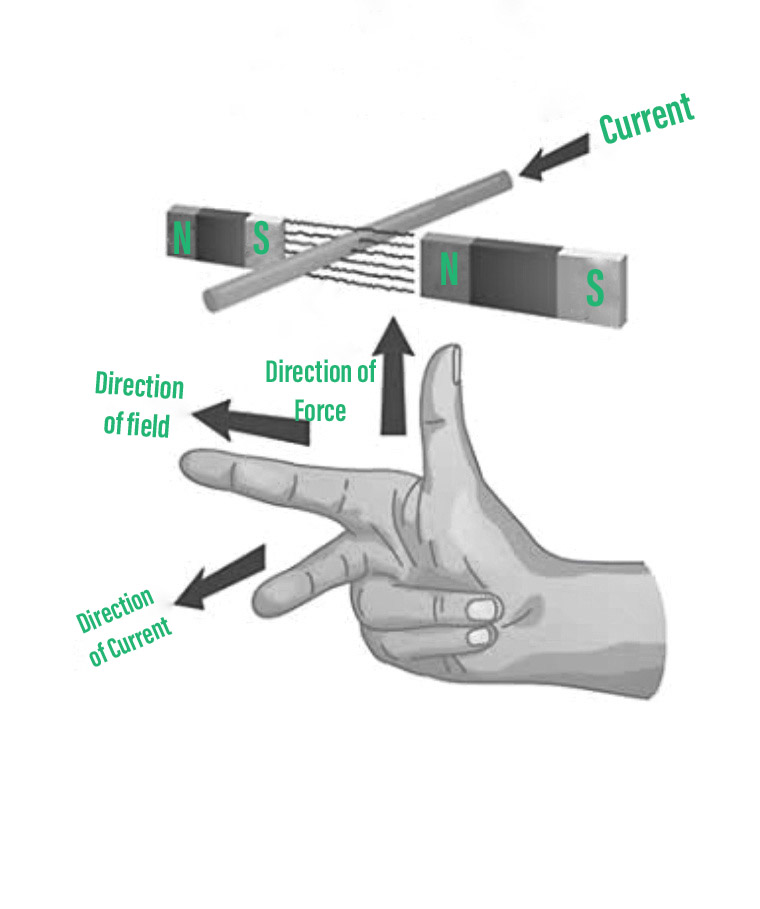
Fleming’s Right Hand Rule may be used to identify the direction of the induced current produced in the coil: “Stretch the thumb, first finger, and centre finger of your right hand such that they are perpendicular to each other. The first finger points in the direction of the magnetic field, the thumb in the direction of conductor velocity, and the middle finger in the direction of induced current.”
The coil of the electric generator is spun in a magnetic field to generate induced current. The resultant induced current fluctuates in amplitude and direction at a rate of thousands of times per second. Alternating current is the name given to this sort of energy (AC).
Direct current DC is used when the current produced by the electric generator does not change in direction or quantity. Depending on the type of current produced by the electric generator, we have a variety of generators.
Types of Electric Generator: Electric generators generate both alternating current (AC) and direct current (DC). Electric generators are classed as follows based on this:
AC Generator
A machine that transforms mechanical energy into electrical energy is known as an AC generator. Mechanical energy is supplied to the AC Generator through steam turbines, gas turbines, and combustion engines. Alternating electrical power in the form of alternating voltage and current is the output.
Principle of AC Generator
AC generators function on Faraday’s law of electromagnetic induction states that electromotive force (EMF or voltage) is created in a current-carrying wire that cuts a uniform magnetic field. Rotating a conducting coil in a static magnetic field or rotating the magnetic field enclosing the stationary conductor can both be used to accomplish this. Because it is easier to extract induced alternating current from a stationary armature coil than from a revolving coil.
The EMF generated is determined by the number of armature coil turns, magnetic field intensity, and rotating field speed.
Construction of AC Generator
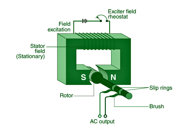
Construction of AC Generator
The roles of each of these AC generator components are listed below.
- Field- The field is made up of conductor coils that receive electricity from the source and generate magnetic flux. The armature is cut by the magnetic flux in the field, which produces a voltage. This voltage is the AC generator’s output voltage.
- Armature- The portion of an AC generator that produces voltage is known as the armature. This component largely comprises of wire coils large enough to handle the generator’s full-load current.
- Prime Mover- The prime mover is the component that drives the AC generator. A diesel engine, a steam turbine, or a motor might all be used as the prime mover.
- Rotor- The rotor is the rotating component of the generator. The rotor is driven by the generator’s prime mover.
- Stator- An AC generator’s stator is the stationary component. To reduce eddy current losses, the stator core is made up of a lamination of steel alloys or magnetic iron.
- Slip Rings- Slip rings are electrical connectors that transport electricity from and to an AC generator’s rotor. They are primarily used to transfer electricity from a fixed device to a revolving one.
Working of an AC Generator
The flux linkage of the armature varies continually as it revolves between the poles of the magnet on an axis perpendicular to the magnetic field. An electric current travels through the galvanometer, slip rings and brushes as a consequence. The galvanometer changes its value from positive to negative. This implies that the galvanometer is receiving an alternating current. Fleming’s Right-Hand Rule can be used to determine the direction of the induced current.
Direct Current Generator (DC Generator): The current produced by this form of electric generator does not alter direction or amplitude. As a result, the frequency of DC is always zero.
Advantages of AC Generators over DC Generators
- Through transformers, AC generators may be simply stepped up and down.
- Because of the step-up functionality, the transmission link size in AC Generators is less.
- The losses in AC generators are lower than in DC machines.
- An AC generator is much smaller than a DC generator.
Sample Question
Question 1: What are the advantages of alternating current versus direct current?
Answer:
The benefits of AC over DC are as follows:
- With the aid of a transformer, AC may be obtained at any required voltage.
- Less electricity is wasted during transmission when utilising AC.
- AC machines are strong and long-lasting, requiring little maintenance.
Question 2: What is the operating principle of an electric generator?
Answer:
The electromagnetic induction principle governs the operation of an electric generator.
Question 3: What is a commutator?
Answer:
It is a device that links the armature of a DC generator to the external circuit and assists in maintaining the current direction in the external circuit. Every half-turn, it switches the connection of the armature ends to the ends of the external circuit.
Question 4: What is electromagnetic induction?
Answer:
The phenomenon of electromagnetic induction occurs when current is generated in a circuit by altering the magnetic flux associated with it.
Question 5: What is an electric generator?
Answer:
A generator is a machine that transforms mechanical energy into electrical energy.
Question 6: Which rule is used to determine the direction of induced current in an AC generator?
Answer:
Fleming’s Right Hand Rule is used to determine the direction of current created in an AC generator.
0 Comments