
Chapter 4 - MOVING CHARGES AND MAGNETISM
Magnetic Force on a Current carrying Wire
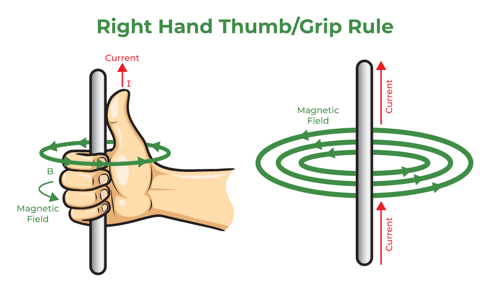
When a charge is moving under the influence of a magnetic field. It experiences forces, which are perpendicular to its movement. This property of charge is exploited in a lot of fields, for example, this phenomenon is used in the making of motors which in turn are useful for producing mechanical forces. These forces are governed by the right-hand thumb rule and are given by the vector products. When a current-carrying wire is exposed to the magnetic field it also experiences forces because the charges are moving inside the conductor.
Force on a Moving Charge in a Magnetic Field
Consider the figure below, this figure shows a conductor that is under the influence of a magnetic field. The conductor is connected to a battery that is continuously causing the current to flow in the wire and the conductor. Since the charges are moving inside the conductor, these charges start experiencing force. Now, these charges are in the conductor and cannot go outside, so the force exerted on these charges is in turn transferred to the force being applied on the conductor.
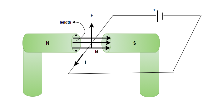
The direction of the force experienced by the conductor is given by the right-hand thumb rule. Now let’s focus on deriving the formula for calculating the force on a current-carrying conductor.
Force acting on each charge flowing inside the conductor in the region where the magnetic field is acting. The total force in this case can be calculated by taking a sum of magnetic forces on the individual charges. Since all the forces will be acting in the same direction, the force on the charges can be added. Consider an individual charge moving with a drift velocity vd. The force acting on this charge is given by,
F = qvBsin(θ)
Considering the magnetic field B, to be uniform over the length “l” of the wire and zero everywhere else. The total magnetic force on the wire, in that case, will be given by,
F = 
Since, each charge is moving with equal velocity, the total force can be re-written as,
F = qvBsin(θ)N
Where N is the number of charges under the influence of the magnetic field. Let’s say “n” is the number of charge carriers per unit volume of the conductors and “V” is the volume of the region of the wire where the magnetic field is acting.
N = nV
Substituting this value in the equation above,
F = qvBsin(θ)(nV)
⇒ F = qvBsin(θ)nV
Also, since the wire is uniform the V = Al, where A is the cross-sectional area and l is the length of the wire under magnetic field. Plugging this value in the equation,
F = qvBsin(θ)nAl
This can be re-arranged as,
F = (nqAv)lBsin(θ)
It is known that nqAv = i, where i is the current in the conductor.
So, the force becomes,
F = ilBsin(θ)
In terms of vector product, this force is given by,
F = i(L × B)
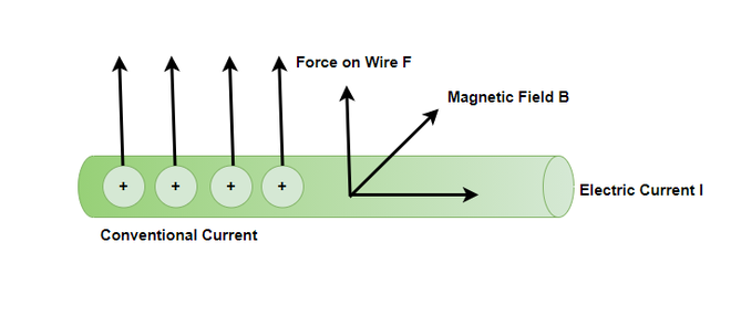
The figure below represents the direction of the force, notice that the direction of the force is perpendicular to both the magnetic field and the direction in which the conductor is carrying current.
Let’s look at some sample problems.
Sample Problems
Question 1: Explain Fleming’s Left-hand Rule.
Answer:
Fleming’s Left-hand rule is used to find the direction of Force. If we put our left thumb, Index finger and middle finger perpendicular to each other in the 3-D space, the thumb will give the direction of the Force, the middle finger will give the direction of current and the Index finger will give the direction of the Magnetic filed.
Question 2: Calculate the force on the wire, given B = 1.50 T, l = 5.00 cm, and I = 20.0 A. The angle between the current and the magnetic field is 90°.
Answer:
The force on the current carrying conductor is given by,
F = ilBsin(θ)
Where, i = 20A, B = 1.5T and l = 5 cm and θ = 90°.
Plugging these values into the equation,
F = ilBsin(θ)
⇒ F = (20)(0.05)(1.5)sin(90°)
⇒ F = (1)(1.5)(1)
⇒ F = 1.5N
Question 3: Calculate the force on the wire, given B = 3 T, l = 50.00 cm, and I = 10.0 A. The angle between the current and the magnetic field is 30°.
Answer:
The force on the current carrying conductor is given by,
F = ilBsin(θ)
Where, i = 10A, B = 3T and l = 0.5 m and θ = 90°.
Plugging these values into the equation,
F = ilBsin(θ)
⇒ F = (10)(0.5)(3)sin(30°)
⇒ F = (5)(0.5)(3)
⇒ F = 7.5N
Question 4: What is the angle between a wire carrying a 4.00-A current and the 2-T field it is in if 50.0 cm of the wire experiences a magnetic force of 8.0 N?
Answer:
The force on the current carrying conductor is given by,
F = ilBsin(θ)
Where, i = 4A, B = 2T and l = 2 m, θ = ? And F = 8.0N
Plugging these values into the equation,
F = ilBsin(θ)
⇒ 8 = (4)(2)(2)sin(θ)
⇒ 8 = 16sin(θ)
⇒ 0.5 = sin(θ)
⇒ sin-1(0.5) = θ
⇒ θ = 30°
Question 5: What is the current in a wire carrying under the 3-T field it is in if 50.0 cm of the wire experiences a magnetic force of 12 N and the angle between the magnetic field and current is 30°?
Answer:
The force on the current carrying conductor is given by,
F = ilBsin(θ)
Where, i =?, B = 3T and l = 0.5 m , θ = 30° and F = 12N
Plugging these values into the equation,
F = ilBsin(θ)
⇒ 12 = (i)(0.5)(3)sin(30°)
⇒ 12(2) = i1.5
⇒ i= 16A
Motion of a Charged Particle in a Magnetic Field
This has been already learned about the interaction of electric and magnetic fields, as well as the motion of charged particles in the presence of both electric and magnetic fields. We have also deduced the relationship of the force acting on the charged particle, which is given by the Lorentz force in this instance. We’ve also learned about the magnetic force acting on a current-carrying conducting rod when it’s exposed to a magnetic field.
What happens, though, when a charged particle travels in the presence of a magnetic field? How can we define such a particle’s trajectory? This will be covered in detail in this article.
When a force acts on a particle, it is said to produce work if a component of the force is directed in the particle’s direction of motion. The magnetic force acts perpendicular to the particle’s motion in the situation under discussion when we have a charged particle carrying a charge q traveling in a uniform magnetic field of size B. In this case, we claim that the magnetic force does no work on the particle and hence no change in the particle’s velocity can be seen. When the particle’s velocity v is perpendicular to the direction of the magnetic field, we may write,
F = q (v × B)
In this case, the magnetic force is directed towards the object’s center of circular motion and functions as a centripetal force. As a result, if v and B are perpendiculars, the particle describes a circle. In other situations, if a component of velocity exists in the direction of the magnetic field B, its magnitude remains constant during the motion, because it is unaffected by a magnetic field. Furthermore, as previously mentioned, the motion caused by the perpendicular component of the velocity is circular in nature.
Circular Motion of a Charged particle in a Magnetic Field
When a charged particle moves through a magnetic field, it experiences a force. What happens if this field is uniform across the charged particle’s motion? Which route does the particle take? In this section, we will look at the circular motion of a charged particle as well as other motions that occur when a charged particle enters a magnetic field.
The simplest instance is when a charged particle moves perpendicular to a uniform, as seen in the picture below. If the field is in a vacuum, the magnetic field is the deciding factor of motion. A charged particle in a magnetic field travels a curved route because the magnetic force is perpendicular to the direction of motion.
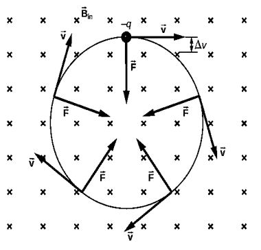
In a region where the magnetic field is perpendicular to the paper, a negatively charged particle travels in the plane of the paper.
This curving path is followed by the particle until it forms a full circle. Another way to think about it is that the magnetic force is always perpendicular to the velocity, thus it does no work on the charged particle. As a result, the particle’s kinetic energy and speed stay constant. The speed is unaffected, but the direction is.
Helical Motion
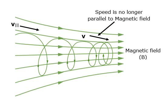
When the velocity vector is not perpendicular to the magnetic field vector, helical motion occurs.
The motion generated when one component of the velocity is constant in amplitude and direction (i.e., straight-line motion) and the other component is constant in speed but changes in direction evenly (i.e., circular motion) is called the Helical motion. It is the result of the combination of straight-line and circular motion.
When a charged particle travels perpendicular to a uniform B-field, as illustrated in, the simplest situation occurs. (If this happens in a vacuum, the magnetic field is the most important element influencing motion.) The magnetic force (Lorentz force) provides the centripetal force in this case, as
Fc = mv2 / r
Since, here sin θ = 1
Then, the magnetic force:
F = qvB
Now, if the Lorentz magnetic force provides the centripetal force, therefore, these force must be equal as:
qvB = mv2 / r
Solve the above expression for r as,
r = mv / qB
The radius of curvature of the path of a charged particle with mass m and charge q traveling at a speed v perpendicular to a magnetic field of strength B is denoted by r, also known as the gyroradius or cyclotron radius. In other words, it is the radius of a charged particle’s circular motion in the presence of a homogeneous magnetic field.
If the velocity is not normal to the magnetic field, then v is the perpendicular component of the velocity. Because the magnetic force is 0 for motion parallel to the field, the component of velocity parallel to the field is unaffected. In a subsequent section on spiral motion, we’ll look at the implications of this situation.
A Cyclotron resonance occurs when a particle experiences circular motion as a result of a homogeneous magnetic field. The word is derived from the name of a cyclic particle accelerator known as a cyclotron, which was demonstrated in.
The cyclotron frequency is defined as the number of cycles a particle finishes itself around a circular circuit per second and may be calculated by solving for v above and substituting in the circulation frequency such that
f = v / 2πr
or
f = qB / 2πm
Hence, The cyclotron frequency is easily expressed in radians per second as:
ω = qB / m
Magnetic Mirror
A magnetic field arrangement in which the field intensity varies along a field line. The mirror effect causes charged particles to bounce back from the high field area, such a phenomenon is called the Magnetic mirror.
Magnetic mirror and Helical Motion
If v denotes the particle’s rotational frequency. Therefore, the time span for one revolution may be expressed as follows:
Time for one revolution, T = 2π / ω = 1 / v
The pitch of a particle is the distance it moves along the direction of the magnetic field in one rotation. then:
Pitch, p = v|| T = 2πmv|| / qB
where v|| is the velocity parallel to the magnetic field.
Sample Problems
Problem 1: Describe how a charged particle would move in a cyclotron if the frequency of the radio frequency (rf) field was doubled.
Solution:
The resonance requirement is violated and the time period of the radio frequency (rf) field is half when the frequency of the radio frequency (rf) field is doubled. As a result, radio frequency completes the cycle in the time it takes a particle to complete half a rotation inside the D’s.
Problem 2: Out of protons, neutrons, and electrons which particle may have the lowest frequency of revolution when propelled with the very same velocity normal to the magnetic field?
Solution:
When a charged particle with mass m and charge q is projected in a magnetic field B then it starts revolving with a frequency of,
f = Bq / 2πm
As a result, a high q/m ratio indicates a higher frequency, and an electron has the highest q/m ratio of the three due to its low mass. The electron’s frequency will be the highest.
Problem 3: When a proton travels in a uniform magnetic field, its velocity changes but its kinetic energy does not. Why?
Solution:
The magnetic force will be perpendicular to the direction of the proton’s travel. We know that when the force acting is perpendicular to the direction of the moving charge, the work done is zero. It indicates that kinetic energy remains constant. The force can alter the direction (velocity) of a proton but not its speed (magnitude). As a result, momentum and velocity shift.
Problem 4: Can a magnetic field accelerate a charged particle? Is it possible to enhance its speed?
Solution:
The magnetic field accelerates the charged particle by altering its velocity direction. The charged particle’s speed is unaffected by the magnetic field. The magnetic field has no effect on speed since it exerts a force perpendicular to the motion. As a result, the force cannot accomplish work on the particle. As a result, the particle’s kinetic energy cannot be changed. Therefore, it is unable to adjust the speed.
Problem 5: What is Lorentz Force? Explain.
Solution:
Lorentz force, the force exerted on a charged particle q travelling with velocity v through an electric and magnetic field E and B. The Lorentz force (named after the Dutch scientist Hendrik A. Lorentz) is the total electromagnetic force F on the charged particle, and it is given by,
F = qE + qv × B
The electric field contributes the first term. The magnetic force, which has a direction perpendicular to both the velocity and the magnetic field, is the second term. Magnetic force is proportional to q as well as the size of the vector cross product v × B. The amount of the force equals qvB sin in terms of the angle between v and B.
The velocity of a charged particle in a uniform magnetic field is an intriguing consequence of the Lorentz force. If v is perpendicular to B (i.e., there is a 90° angle between v and B), the particle will follow a circular trajectory with radius r = mv/qB. The particle orbit will be a helix with an axis parallel to the field lines if the angle is less than 90°.
If ϕ is 0, there will be no magnetic force acting on the particle, which will continue to travel along the field lines undeflected. Particle accelerators using charged particles, such as cyclotrons, take use of the fact that particles move in a circular orbit when v and B are at right angles.
Biot-Savart Law
The Biot-Savart equation expresses the magnetic field created by a current-carrying wire. This conductor or wire is represented as a vector quantity called the current element. Lets take a look at the law and formula of biot-savart law in detail,
Biot-Savart Law
The magnitude of magnetic induction at a place caused by a tiny element of a current-carrying conductor is stated in the law.
- Directly proportional to the current
- Directly proportional to the length of the element
- Directly proportional to the sine of the angle between the element and the line joining the center of the element to the point and,
- Inversely proportional to the square of the distance of the point from the center of the element
dB α I
dB α dl
dB α sinΘ
dB α 1 / r2
∴ dB α IdlsinΘ / r2
∴ dB = KIdlsinΘ / r2 (K is constant)
Derivation
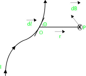
Consider a conductor of any form carrying a current (I) and a tiny length element (dl) (refer to below image). The current flow is depicted vertically upward.
Let (P) be any point a distance (r) from the current-carrying element, and (r) be the position vector of (P) with respect to the current element, and be the angle between (dl) and (r), in the direction of the current.
Biot – Savart`s Law
According to Biot – Savart Law, the magnetic induction at point (P) is given by,
dB = KIdlsinΘ / r2 ⇢ (1)
Here, K is Constant and its value depends on the system of units and also the medium in which the conductor is situated.
In the SI system, the constant K for vacuum or air is written as [μo / 4π] where μ0 is called the permeability of vacuum or free space.
Substituting K in Eq (1) We get,
dB = μ0 / 4π [IdlsinΘ / r2] ⇢ (2)
SI unit of μ0 Wb / Am. It`s value is 4π X 10-7 Wb / Am
(μ0 / 4π = 10-7 Wb / Am)
The direction of magnetic induction is perpendicular to the plane of the figure and directed inside the plane. (as per the right-hand Thumb rule.)
In vector form,

Where [r] is the vector drawn from the center of the element to the point and [dl] is the length of the element, in the direction of the current. The total magnetic induction at a point P due to the entire conductor is found by adding the contribution of all such element [dl] and is expressed as,


Summation is replaced by ∫

Now, The magnitude of the magnetic induction due to an infinitely long and straight conductor, carrying a current I, at a point at a distance ‘a’ from the conductor is given by,

Applications of Biot – savart law
Following are some importance of the Biot-Savart law:
- We may utilize Biot–Savart law to determine magnetic responses at the atomic or molecule level.
- It may be utilized in aerodynamic theory to determine the velocity promoted by vortex lines.
- This rule may be used to compute the magnetic field produced by a current element.
Importance of Biot-Savart Law
Following are some importance of the Biot-Savart law:
- In electrostatics, the Biot-Savart law is analogous to Coulomb’s law.
- The legislation also applies to extremely tiny conductors that convey current.
Conceptual Problems
Question 1: State Biot – savart’s law and write it in vector form.
Answer:
Law statement : The Magnitude of magnetic induction at a point due to a small element of a current-carrying conductor is, directly proportional to the current, directly proportional to the length of the element, directly proportional to the sine of the angle between the element and the line joining the center of the element to the point and, inversely proportional to the square of the distance of the point from the center of the element.
Boit savart Law in vector form is given by:
Question 2: State any two applications of Biot savart’s law.
Answer:
Applications of Biot savart`s law are:
- To calculate magnetic responses at the atomic or molecular level, we can use Biot–Savart law, and
- It may be used in aerodynamic theory to calculate the velocity induced by vortex lines.
Sample Problems
Question 1: A current of 5A is flowing from south to north in a wire kept along the north-south direction. Find the magnetic field due to a 1cm piece of wire at a point 2m northeast from the piece of wire.
Solution:
Given Data: I = 5A
r = 2m
Θ = 45°
dl = 1cm = 1 × 10⁻² m
To find: Magnetic field (dB)
Formula: dB = μ0 / 4π [IdlsinΘ / r2]
Calculation: From formula,
dB = 10-7 × 6 × 10-2 × sin45° / 22
= 8.84 × 10⁻¹⁰ T
The Magnetic field due to wire at point is 8.84 × 10⁻¹⁰.
Question 2: A long straight wire carries a current of 35A. What is the magnetic field B at a point 20cm from the wire?
Solution:
Given Data: I = 35A
a = 30cm = 0.3m
To find: The magnitude field (B)
Formula: B = μ0 / 2π (I / a)
Calculation: From formula,
B = 4π × 10-7 / 2π (35 / 0.3)
= 2 × 10⁻⁷ (116.66)
B = 233.32 × 10⁻⁷ T
The magnetic field at point 30cm is 233.32 × 10⁻⁷ T.
Question 3: A long straight wire in the horizontal plane carries a current of 50A in the north-south direction. Give the magnitude and direction of B at a point 3m east of the wire.
Solution:
Given Data: I = 50A
a = 3m
To find: Magnitude and the direction of B
Formula: B = μ0I / 2πa
Calculation: From Formula,
B = 4π × 10-7 × 50 / 2π × 3
= 2 × 10-7 × 50 / 3
B = 3.333 × 10⁻⁶ T
It acts in the vertically upward direction, so direction is downward.
“Note: The direction of the magnetic field is always in a plane perpendicular to the line of element and position vector.”
The magnitude of B is 4 × 10⁻⁶ T and the direction is vertically downward.
Question 4: Two long straight parallel wires in vacuum are 4m apart and carry currents 6A and 8A in the same direction. Find the neutral point, i.e., the point at which the resultant magnetic induction is zero.
Solution:
Given Data: I1 = 4A
I2 = 8A
r = 4m
To find: neutral point ( the point at which resultant magnetic induction is zero )
Formula: (i) B1 = μ0 / 4π (2I1 / r1)
(ii) B2 = μ0 / 4π (2I2 / r2)
The current flowing through the wire is all going in the same direction. As a result, at any location between the two wires, the two magnetic inductions B1 and B2 will have opposing orientations. As a result, the point must be located between the two wires.
For the resultant magnetic induction to be zero, we must have B = B2
Let the corresponding point (The neutral point) be at distance r1 from the first wire and r2 from the second wire.
Calculation:
B = μ0 / 4π ( 2I1 / r1) and B2 = μ0 / 4π ( 2I2 / r2)
Now, B1 = B2
∴ I1 / r1 = I2 / r2
∴ r2 / r1 = I2 / I1
∴ r2 / r1 = 8A / 4A
= 2
∴ r2 = 2r1
But, r1 + r2 = r
∴ r1 + 2r1 = 4m
∴ r1 = 4/3m and r2 = 8/3m
The neutral point lies at a distance of 4/3m from the wire carrying a current of 4A.
Magnetic Field on the Axis of a Circular Current Loop
Moving charges is an electric current that passes through a fixed point in a fixed period of time. Moving charges are responsible for establishing the magnetic field. The magnetic field is established due to the force exerted by the flow of moving charges. As the magnetic field is established moving charges start acting like a magnet.
Magnetic Effect of Current when current is flowing through the conductor, a magnetic field is established around it. This phenomenon is called the magnetic effect of electric current.
Behavior of Charged particle in the magnetic field
When the charged particle moves through the magnetic field it experiences a force on it. When the charged particle q moves with the velocity v in the magnetic field B and the velocity of the particle is perpendicular to the direction of the magnetic field then force acting on it is given by F = q(v × B). Hence, the magnetic force is directed towards the circular motion of the particle and acts as a centripetal force. Thus if v and B are perpendicular to each other, the particle moves in a circle. Thus, the particle moves in the helical motion when the two components are acting perpendicular. When the particle moves along the direction of the magnetic field then no effect is felt upon it.
Ampere’s Circuit Law
The line integral of the magnetic field in a closed path is equal to the μ0 times the net current passing through that closed path or loop.

Biot – Savart Law
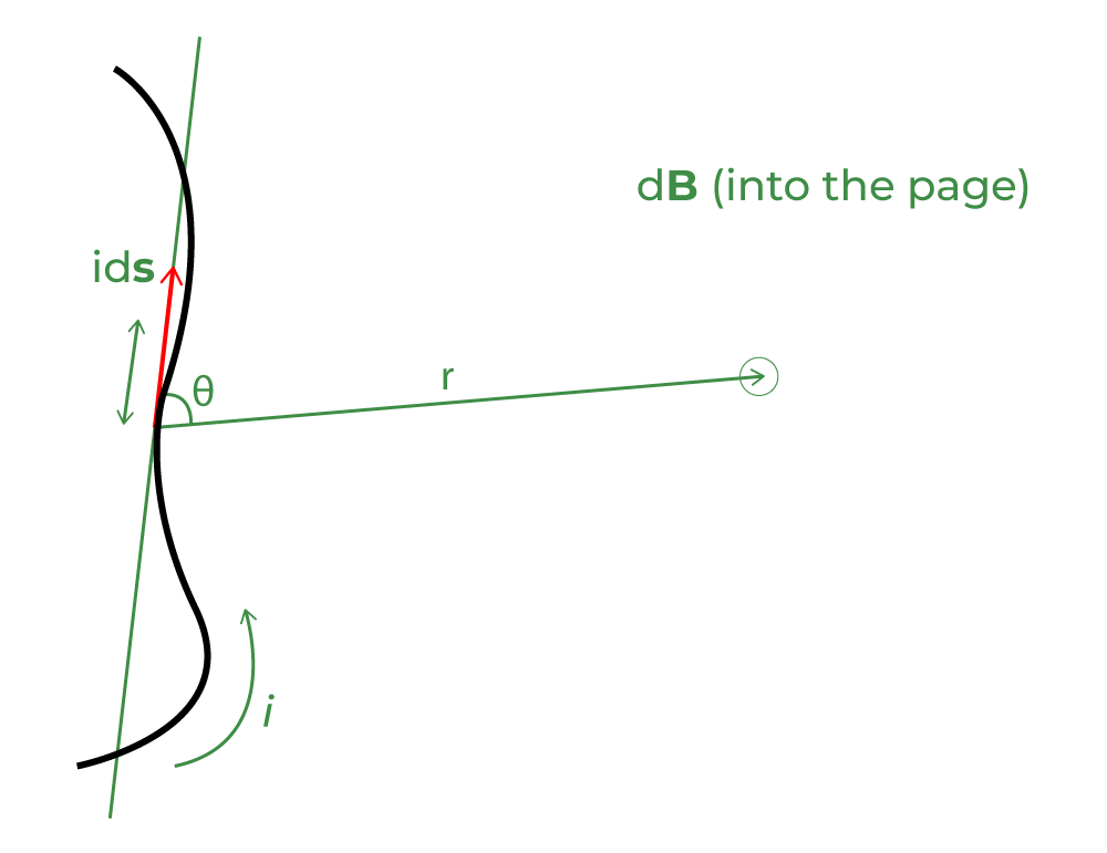
According to Biot-Savart law magnetic field at a point due to very small current element dl depends upon
- directly proportional to the current(I)
dB ∝ l…….eq(1)
- directly proportional to the length of an element(dl)
dB ∝ dl…….eq(2)
- directly proportional to sinθ
dB ∝ sinθ……..eq(3)
- inversely proportional to r2
dB ∝ (1 / r2)……..eq(4)
combining equations 1,2,3 and 4 we get
dB ∝ (I dl sinθ ) / r2
dB = (k I dl sinθ ) / r2
If, k =1
dB = ( I dl sinθ ) / r2
The magnetic field dB at a point P associated with a length element dl of a wire carrying a steady current I is given by
dB = 
μ0 is the permeability of free space
μ0/4π = 10-7 Henry/meter
Biot – Savart law in vector form

The direction of  is perpendicular to the plane determined by
  and
and  .
.
Application of Biot-Savart’s Law
- This law is used to calculate the magnetic reactions on the molecular or atomic level.
- It can be used in aerodynamics for determining the velocity of vortex lines.
Importance of Biot-Savart’s Law
- This law is applicable for even very small current carrying conductors.
- This law resembles Coulomb’s law in electrostatics.
- This law is used in the symmetric current distribution.
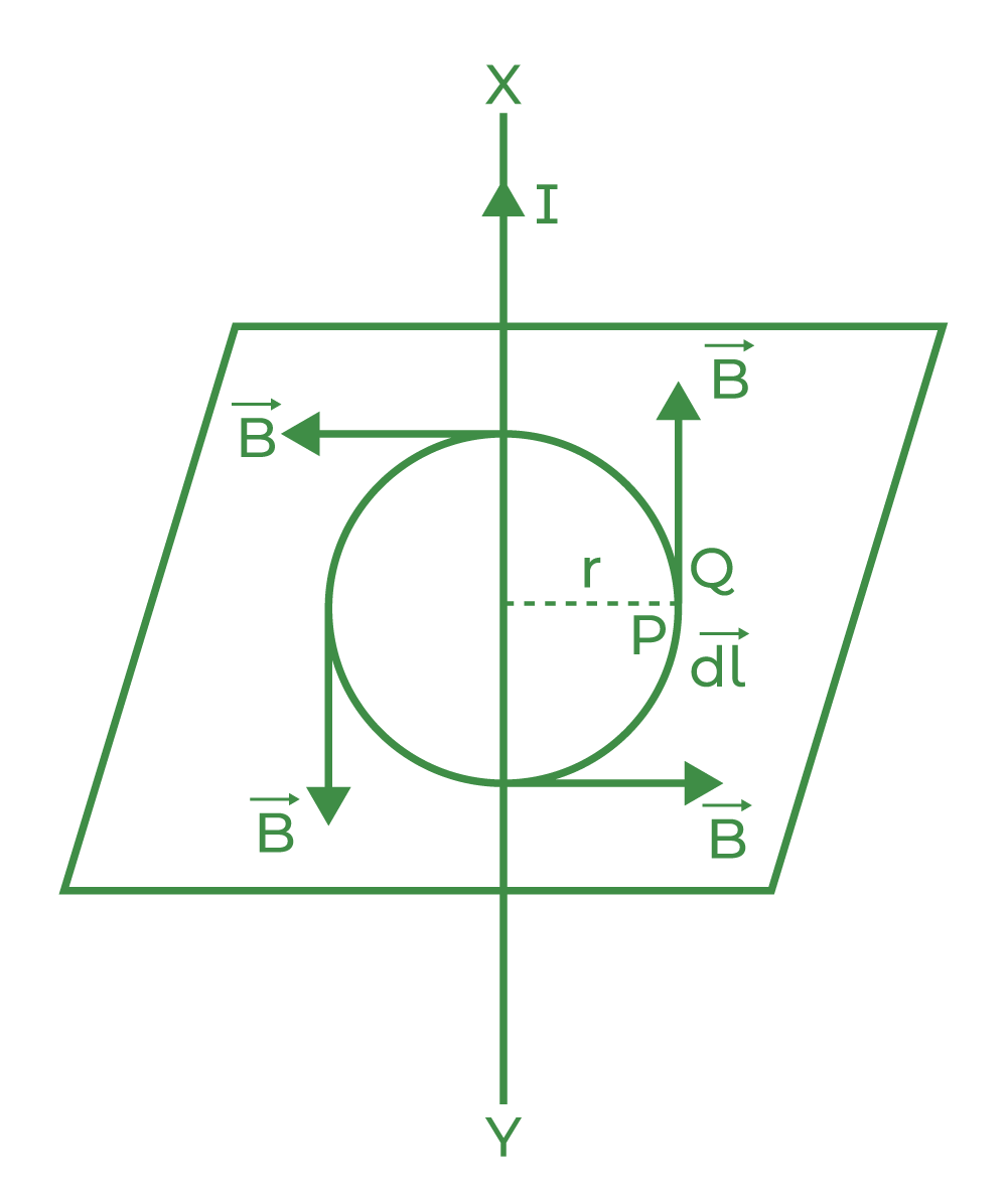
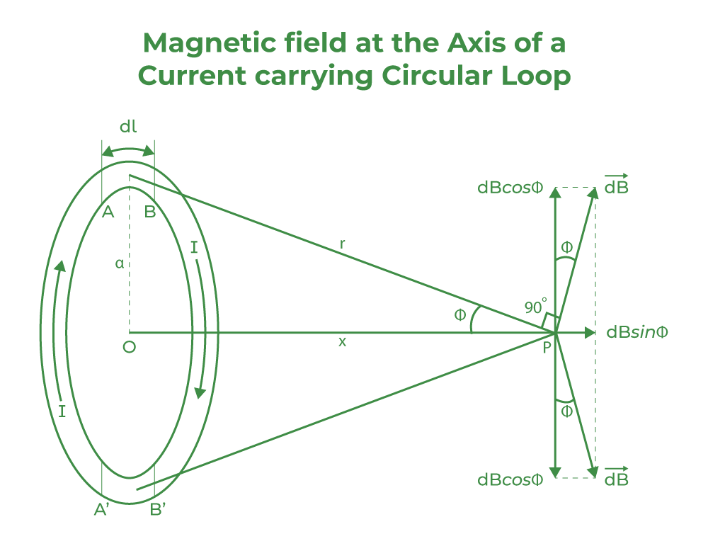
Magnetic Field on the Axis of a Circular Current Loop
Let us suppose a circular current loop of radius a and magnetic field at a distance of x unit along its axis is required then,
a is the radius of the circular current loop
I is the current flowing through the circular current loop
dB1 and dB2 are the magnetic fields
dl is the very small length of wire of the loop
x is the distance of P from center O of the loop
From the Biot Savart law,
The direction of the magnetic field is perpendicular to the plane determined by dl and r
Therefore, r2 = x2 + a2
Magnetic field due to current element dl remains same
dB1 = dB2 = 
dB1 = dB2 = 
The vertical component cancel the effect of each other
The magnetic field at point P is given by
B = ∫ dB sinθ
B = ∫ [ sinθ = a / r ]
B =  ×∫dl
×∫dl
B =  [ l = 2πa and r = (x2 + r2)1/2]
B = 
B = 
B = 
Case 1: If the observation point is at the center of the loop
At the center of loop x = 0
B = 
B = 
Case 2: If the observation point is far away from the loop
If the observation point is far away from the loop, then a << x so, a2 can be neglected in comparison to x2
B = 
Note:
If there is a coil of N turns then the magnetic field is given by
B = 
Right-Hand Thumb Rule
If we hold the thumb of the right hand mutually perpendicular to the grip of the fingers such that the curls of the fingers represent the direction of current in the wire loop, then the thumb of the right hand will point in the direction of the magnetic field near the center of the current loop.
Practise Problems based on Magnetic Field on the Axis of a Circular Current Loop
Problem 1: Magnetic field intensity at the center of a coil of 50 turns, radius 0.5 m, and carrying a current of 2A is ________.
Solution:
Magnetic field at the center of the coil is given by
B =

= (4 π ×10-7 × 2 × 50) / (2 × 0.5)
B = 1.25 × 10⁻⁴ T
Problems 2: An electric current is flowing in a circular loop of radius r. At what distance from the center on the axis of the loop will the magnetic field be 1/8th of its value at the center?
Solution:
Magnetic field at the center of the circular loop B1 is given by
B =
Magnetic field at any distance x of the circular loop B2 is given by
B =
According to the question
B1 = (1/8) B2
= (1/8)
r3 / (r2 + x2)3/2 = 1/8
[ r / (r2 + x2)1/2 ]3 = 1/8
r / (r2 + x2)1/2 = 1/ 3√8
r / (r2 + x2)1/2 = 1/2
2r = (r2 + x2)1/2
Squaring both sides
4r2 = r2 + x2
x2 = 3r2
x = √3 r

Problem 3: Magnetic field intensity at the center of a circular current loop, radius 0.4 m, and carrying a current of 3A is ________.
Solution:
Magnetic field at the center of the coil is given by
B =
B = (4 π ×10-7 × 3) / (2 × 0.4)
B = 4.71×10⁻⁶ T
FAQs on Magnetic Field
Question 1: Where is the intensity of the magnetic field strongest in a circular loop?
Answer:
The intensity of magnetic field is strongest at the center of the circular loop.
Question 2: State the equation for the magnetic field on the axis of the current carrying coil of N turns.
Answer:
The equation for the magnetic field on the axis of the current carrying coil is given by
B =

Question 3: State the equation for the magnetic field on the axis of the current carrying loop.
Answer:
The equation for the magnetic field on the axis of the current carrying loop is given by
B =

Question 4: State Biot Savart law and its formula.
Answer:
The magnetic field dB at a point P associated with a length element dl of a wire carrying a steady current I is given by
dB =

Question 5: What do we mean by circular current loop?
Answer:
Any circular loop is made by coiling small straight wires large number of times. This circular coil produces magnetic field when current flows through these wires. The magnetic field lines produced are straight and are perpendicular to the plane of the coil.
Ampere’s Circuital Law and Problems on It
André-Marie Ampere, a French physicist, proposed Ampere’s Circuital Law. Ampere was born in Lyon, France, on January 20, 1775. His father educated him at home, and he showed an affinity for mathematics at a young age. Ampere was a mathematician and physicist best known for his work on electrodynamics, Ampere’s Law, and the confirmation and amplification of Oersted’s work on the relationship between electricity and magnetism.
He was also the inventor of the astatic needle, which is a key component of the modern astatic galvanometer. He was the first to show that a magnetic field is formed when two parallel wires are charged with electricity. He is widely regarded as one of the pioneers in the field of electromagnetic. The ‘ampere,’ a unit of electric current, is named after him.
Ampere’s Circuital law
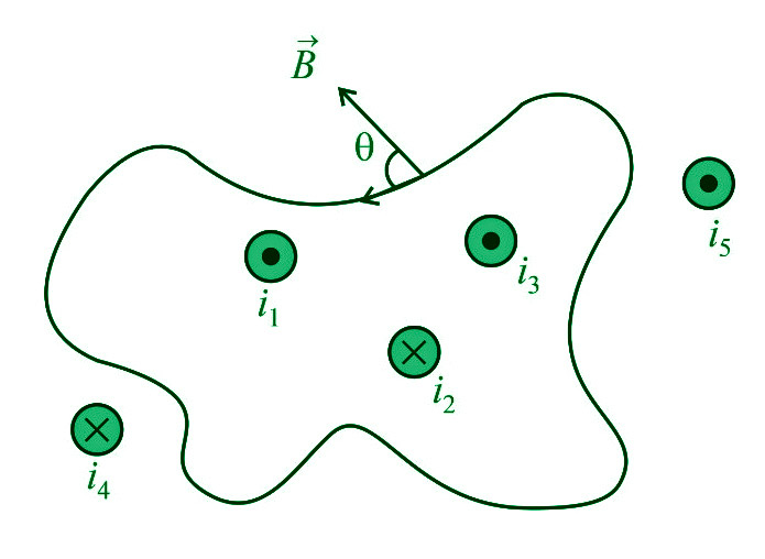
“Around every closed curve, the line integral of the magnetic field B is equal to μ0 times the net current I threading through the region contained by the curve.”
i.e.
∮B’dl’ = μ0∑i = μ0(i1+i3–i2)
where,
μ0 denotes the permeability of empty space and B denotes the magnetic field at a location on the surface’s boundary that forms an angle ” with the length element ‘dl’.
The ‘Amperian loop’ is also known as the sum of all the B’dl’ products across the whole loop.
Note:
- (i1+i3–i2) is the total current that crosses the above loop. Any current beyond the region is not included in net current, but we must include the magnetic field owing to all currents when calculating B’dl’ (both inside as well as outside the loop currents)
- Sign convention: (positive outward current, negative inward current)
- This rule only applies to stable currents. This law stays true regardless of the size and shape of the current-enclosing closed route (Amperian loop).
- The phrase B’dl’=0 does not imply that the magnetic field B is zero everywhere along the path, but it does imply that no net current is travelling through it.
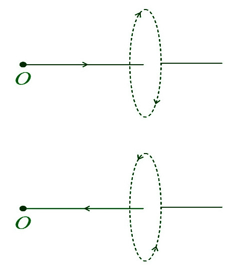
- The closed path’s direction is clockwise when the stream is flowing away from the observer. The closed route is anticlockwise when the current is flowing in the direction of the observer.
Alternative Form of Ampere’s Circuital Law
We know that,
∮B’dl’=μ0∑i=μ0(i1+i3–i2)
By using B’=μ0H’ (where H= magnetizing field)
∮B’dl’=μ0∑i=μ0(i1+i3–i2)
∮μ0H’.dl’=μ0Σi
∮H’.dl’=Σi
Inconsistency of Ampere’s Circuital Law
Ampere’s Law is only applicable for constant current or when the electric field does not vary with time, according to James Clerk Maxwell. Consider a parallel plate capacitor being charged by a battery to demonstrate the discrepancy. Time-varying current travels across connected wires during charging.
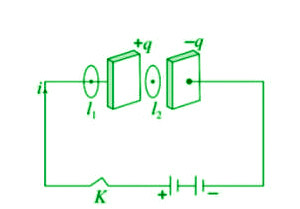
Applying Ampere’s Law for loop l1 and l2
For loop 1− ∮l1B’⋅dl’=μ0i
For loop 2− ∮l2B’⋅dl’=0 (i=0 between the plates).
However, it is noticed that a magnetic field exists between the plates when they are charged or discharged in practice. As a result, Ampere’s Law fails.
i.e.
∮l1B’⋅dl’≠μ0i.
Modified Ampere’s Circuital Law or Ampere – Maxwell’s Circuital Law
During the charging process, Maxwell hypothesized that some current must travel between the capacitor plates. It was given the term displacement current by him. As a result, the updated law is as follows:
∮ B’⋅dl’=μ0(ic+id)
or
∮B’⋅dl’=μ0(ic+ε0 x dϕE/dt)
where;
ic= Conduction current = current due to flow of charges in a conductor and
id= Displacement current =ε0 x dϕE/dt= current due to the changing electric field between the plates of the capacitor.
Note:
- The magnitude of the displacement current (id) equals the size of the conduction current (ic).
- The total of ic and id in a circuit is always continuous, even if they are not continuous.
Application of Ampere’s Circuital Law
The law of Ampere is applied.
- The magnetic field produced by a cylindrical wire must be determined.
- The magnetic field produced by an endless sheet carrying electricity must be determined.
- The magnetic field within a solenoid and a toroid must be determined.
- The magnetic field within a conductor must be determined.
- To determine the forces that exist between current-carrying conductors.
Sample Problems
Problem 1: A long solenoid has 200 turns per cm and carries a current of 2.5A. What is the magnetic field at its centre?
Solution:
B=μ0ni
=4π×10–7×200/10–2×2.5
=6.28×10⁻²Wb/m2.
Problem 2: The average radius of a toroid made on a ring of non-magnetic material is 0.1m, and it has 500 turns. If it carries 0.5A current, what is the magnetic field produced along its circular axis inside the toroid?
Solution:
B=μ0ni; where n=N/2πR
∴B=4π×10–7×500/(2π×0.1)×0.5
=5×10⁻⁴T.
Problem 3: For the solenoid shown in the figure, what is the magnetic field at point P?
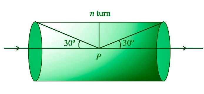
Solution:
B=μ0/4π x 2πni(sinα+sinβ)
From figure α=(90o–30o)=60o and β=(90o–60o)=30o
∴B=μ0ni/2 x (sin60o+sin30o)
=μ0ni/4(√3+1).
Problem 4: The figure shows the cross-sectional view of the hollow cylindrical conductor with inner radius R and outer radius 2R, a cylinder is carrying uniformly distributed current along its axis. What will be the magnetic induction at point P at a distance 3R/2 from the cylinder’s axis?
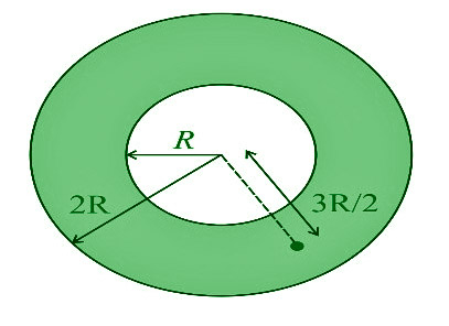
Solution:
By using B=μ0i/2πr x (r2–a2/b2–a2), here r=3R/2, a=R, b=2R
B=μ0i/2π(3R/2)×[(3R/2)–R2/(2R)2–R2]
=5⋅μ0i/36πr
Problem 5: What is the strength of the magnetic field at a location on the axis of an infinitely long, straight, thin-walled tube carrying current I?
Solution:
Because the tube is hollow on the inside and the Amperian loop does not carry any current, so magnetic field is zero.
Force between Two Parallel Current Carrying Conductors
Moving charges produce an electric field and the rate of flow of charge is known as current. This is the basic concept in Electrostatics. The magnetic effect of electric current is the other important phenomenon related to moving electric charges. Magnetism is generated due to the flow of current. Magnetic fields exert force on the moving charges and at the same time on other magnets, all of which have moving charges. When the charges are stationary, their magnetic field doesn’t affect the magnet but when charges move, they produce magnetic fields that exert force on other magnets.
Magnetism is produced by the movement of charges around a conductor. Magnetism is often a property exhibited by magnets and caused by moving charges that force objects to be pulled or pushed away.
Force in a Magnetic Field
The movement of charges generates a magnetic field and the magnetic force exerted in that field is referred to as the force produced by the magnetic field. The fundamental property of matter that allows it to produce and experience electrical and magnetic effects is called charge. The magnetic field of a magnet is a specific area in space where the magnet exerts its magnetic effect. Assume that there is a point charge q that is present in the magnetic field B (r) and the electric field E (r) and that it is traveling at a velocity of v while being placed at r at a particular time t. The force exerted by both of them on an electric charge q can be expressed as,
F = q [E(r) + v × B(r)] = FElectric + Fmagnetic
This formula was stated by H.A. Lorentz for the force due to the electric field, based on the extensive experiments of Ampere and others. It is also called the Lorentz force.
Force between Two Parallel Current Carrying Conductor
Magnetic field is generated by a current-carrying conductor. Another current-carrying conductor experiences force as a result of the external magnetic field. Therefore, we can say that any two current-carrying conductors will exert a magnetic force on one another when they are put close to each other.
Read More: Magnetic Field due to Current Carrying Conductor
The forces between two parallel currents are of two types:
- Attractive: When current is flowing in the same direction in both wires then attractive force is exerted.
- Repulsive: When current is flowing in the opposite direction in both wires then repulsive force is exerted.
-(1).png)
Consider two parallel current-carrying wires, separated by a distance ‘d’, such that one of the wires is carrying current I1 and the other is carrying I2. From previous studies, we can say that wire 2 experiences the same magnetic field at every point along its length due to wire 1. Using the Right-Hand Thumb rule we can determine the direction of magnetic force.
The magnitude of the field due to the first conductor can be calculated using Ampere’s Circuital Law by,
Ba = μ0I1 / 2πd
The force on a segment of length L of wire 2 due to wire 1 can be given as,
F21 = I2LB1 = (μ0I1I2 / 2πd) L
Similarly, we can calculate the force exerted by wire 2 on wire 1. We see that wire 1 experiences the same force due to wire 2 but the direction is opposite. Thus,
F12 = -F21
Also, the currents flowing in the same direction make the wires attract each other and that flowing in the opposite direction makes the wires repel each other. We can find the magnitude of the force acting per unit length by the formula,
Fba = μ0IaIb / (2πd)
where,
d is the distance between two conducor
Ia is the current in wire 1
Ib is the current in wire 2
Force between Two Parallel Current Carrying Sheets
Consider two parallel Sheets carrying currents producing a uniform magnetic field of induction B between the planes. Outside this space, there is no magnetic field. The magnetic force acting per unit area of each plane is
F = B2 / 2μ0
The magnetic field due to one of the sheets is (1/2) B. The force on the sheet is given by,
F = (1/2)B × i × Length × Breadth
F = (B2 / 2μ0) per unit area.
The above-mentioned formula is similar to F = BIl on a straight wire.
Also, Check
Solved Examples on Current-Carrying Wire
Example 1: Two current-carrying wires of equal length are parallel to one another and spaced 4.8 m apart, producing a force of 1.5 10-4 N per unit length. What will be the force per unit length on the wire if the current in both wires is doubled and the distance between the wires is halved?
Solution:
Force per unit length on both wires fab = fba = f = 1.5 × 10⁻⁴ N
distance (d) = 4.8m
The force per unit length on wires is given as,
fab = fba = f = μ0IaIb / 2πd —(1)
when the current in both wires is doubled,
I’a = 2Ia
I’b = 2Ib
Distance between the wires is halved,
d’ = d/2
equation (1) can be written as,
f’ab = f’ba = f’ = μ0I’aI’b / 2πd’
f’ = 2 × (μ0×2Ia×2Ib / 2πd)
f’ = 8 × (μ0×Ia×Ib / 2πd)
f’ = 8f
f’ = 8 × 1.5 × 10-4 N
f’ = 12 × 10-4 N
Example 2: Two very long wires are placed parallel to each other and separated by a distance 3m apart. If the current in both the wires is 6A, then the force per unit length on both wires will be:
Solution:
Current in both the wires Ia = Ib = 6A
distance (d) = 3m
The force per unit length is given as,
fab = fba = f = μ0IaIb / 2πd —(1)
from equation (1),
f = (μ0×6×6) / (2π×3)
f = (6μ0/π) × (4/4)
f = 24μ0 / 4π —(2)
we know,
μ0/4π = 10-7 T – m/A —(3)
from equation (2) and (3),
f = 24 × 10-7 N
Example 3: If 8 A of current flows in the first wire, 11 A of current flows in the second wire. The distance between two wires is 15 m and find the magnetic force between the two wires.
Solution:
Given that
Current in the first wire Ia = 8 A
Current in the second wire Ib = 11 A
Distance between two wires d = 15 m
F/L = μ0 × Ia × Ib /(2πd)
= 4π x 10-7 × 8 × 11/(2π × 15)
= 176 × 10-7/15
=11.733 × 10⁻⁷ N
Therefore, the magnetic force between two wires is 11.733 × 10⁻⁷ N.
Example 4: Two long and parallel straight wires A and B carrying currents of 5 A and 3 A in the same direction are separated by a distance of 6 cm. Estimate the force on a 12 cm section of wire A.
Solution:
Current in wire A, I1 =5 A
Current in wire B, I2 =3 A
Force exerted on 10cm section of wire A,
B = μ0 × 2 × I1× I2 / (4πd)
= 4π x 10-7 × 2 × 5 × 3/(4π × 6 × 10-2)
= 5 × 10⁻⁵ T
The Attractive force is normal from A towards B, because current direction is same.
Example 5: Two wires carry currents of 50 A and 70 A respectively and they repel each other with a force of 0.25 N/m. The distance between them will be
Solution:
Current in wire A, I1 = 50 A
Current in wire B, I2 = 70 A
Magnetic Force, F = 0.25 N/m
F = μ0 × 2 × I1× I2 / (4πd)
0.25 = 4π x 10-7 × 2 × 50 × 70/(4π × d)
0.25 × d = 7 × 10⁻⁴
d = 2.8 × 10⁻³ m
FAQs on Current-Carrying Wire
Question 1: Define Magnetic field.
Answer:
The magnetic field or magnetic induction by that material or by that current is the area or space around the current-carrying wire/moving electric charge or surrounding the magnetic object in which force of magnetism can be felt by other magnetic materials.
Question 2: Determine the force between two current-carrying wires.
Answer:
Ampere’s law states that, if 1 ampere of current flows through each of two parallel conductors of infinite length, separated by 1 meter in empty space free from other magnetic fields, causes a force of exactly 2 × 10⁻⁷ N/m on each conductor.
Question 3: What is the relationship between the currents in the two wires?
Answer:
The two wires carrying current in the same direction attract each other, and they repel each other if the currents flows in opposite direction.
Question 4: Which force is acting between two parallel current-carrying conductors?
Answer:
An external magnetic field exerts a force on a current-carrying conductor and the Lorentz force formula governs this principle. Thus, we can say that any two current carrying conductors when placed near each other, will exert a magnetic force on each other.
Current Loop as a Magnetic Dipole
When a charge move it generates an electric field and the rate of flow of charge is the current in the electric field. This is the basic concept in Electrostatics. The magnetic effect of electric current is the other important concept related to moving electric charges. Magnetism is generated due to the flow of current. Magnetic fields exert force on the moving charges and at the same time on other magnets, all of which have moving charges. When the charges are stationary, their magnetic field doesn’t affect the magnet but when charges move, they produce magnetic fields that exert force on other magnets.
The movement of charges generates magnetism around a conductor. Generally, magnetism is a property shown by magnets and produced by moving charges, which results in objects being attracted or pushed away.
Magnets and Magnetic fields
Moving charge creates a magnetic field and the force created in a magnetic field is called Magnetic Force. A charge is a basic property associated with the matter due to which it produces and experiences electrical and magnetic effects. A particular region in space around the magnet where the magnet has its magnetic effect is called the magnetic field of the magnet.
Assume that there is a point charge q (moving with a velocity v and, located at r at given time t) in presence of both the electric field Er and the magnetic field Br. The force on the electric charge q due to both magnetic field and electric field can be written as,
F = q [Er + v × Br] ≡ EElectric + Fmagnetic
This is formula was stated by H.A.Lorentz for the force due to the electric field, based on the extensive experiments of Ampere and others. It is also called the Lorentz force.
Characteristics of Magnets
Characteristics of a Magnets are:
- Similar poles of a magnet repel each other, when two north poles of bar magnets are brought close to each other, they move away from each other.
- Opposite poles of magnets attract each other, when two opposite poles like the north pole and south pole of two magnets, are brought close to each other, they attract each other.
- In a magnet, the north pole and south pole cannot be separated. This is because every magnet, even when broken into pieces, will create a dipole from each piece. Each piece of the magnet will always have a north pole or a south pole.
- When a magnet is freely suspended, the north pole of the magnet will point to the geographical north and the south pole of the magnet will point to the geographical south.
- The magnetic field is maximum at the poles and minimal at the middle of the magnet.
Magnetic Dipole and Magnetic Dipole Moment
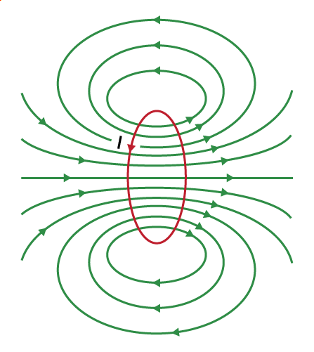
A magnetic dipole is formed by placing a magnetic north pole and south pole closer together, where the product of the magnetic pole charge and distance is constant. Andre-Marie Ampere gave the idea that a current loop can act as a magnetic dipole. This phenomenon is explained by Ampere with the help of the circular movement of current through the wire. It is similar to the magnetic dipole with the magnetic field line straight at the center of the loop. If the current flows in a circular loop inside a magnetic field it behaves as a magnetic dipole. When an electron rotates around the positively charged nuclei, it forms a magnetic dipole. The direction of the magnetic field lines is determined by the direction of current flow in the wired loop.
In a magnetic dipole, two opposite magnetic charges (bar magnet) are kept at a very short distance. Magnetic Dipole Moment is defined as the ability of a magnetic dipole to align itself with the magnetic field outside. The magnetic dipole moment is defined as the maximum amount of torque caused by magnetic force on a dipole that arises per unit value of the surrounding magnetic field in a vacuum. It is a vector quantity and its direction is from the north pole to the south pole. Its SI unit is Ampere-meter2 and its cgs unit is ergs per gauss.
The torque of the dipole can be written as,
τ = M × B
where,
τ is the torque acting on the dipole
M is the magnetic moment
B is the outside magnetic field
A magnetic dipole is the presence of both poles of a magnet, this creates a magnetic field. For example, when a bar magnet is broken into pieces, each piece will act as a magnetic dipole individually, and every piece will carry a north and a south pole.
Current loop as a Magnetic Dipole and Its Dipole Moment
When a current passes through a circular loop it is considered a magnetic dipole. It works through the geometry of the ring which tries to align the magnetic object around it and creates a magnetic field or lines of the magnetic field. The magnetic dipole moment of a current loop is defined as the product of the current in the loop and the area of the loop.
μ = nIA
where,
n is the number of turns in the loop
I is the current in the loop
A is the area inside the loop
The SI unit of the dipole moment is ampere-meter2, and the cgs unit for the dipole moment of a current loop is erg/gauss. Where erg is the unit of energy and gauss is the unit of magnetic flux density.
Characteristics of Magnetic Field Created by a Current Loop
Characteristics of a Magnetic Field Created by a Current Loop are:
- The lines are circular near the coil and are straight toward the center of the circular current-carrying coil.
- The magnetic force lines enter from the lower end of the coil and leave from the upper back. The lower end from which the lines seem to be entering is the south pole of the dipole. The upper end, where the lines seem to be leaving is the north pole of the dipole.
- The direction of the dipole moment of the current loop will be in a direction perpendicular to the plane of the current-carrying loop.
- The direction of the magnetic dipole is a vector with the magnetic field moving from the south pole to the north pole.
Current Loop as a Magnetic Dipole
The circular current loop acts as a magnetic field due to the current moving in the circular direction or in a loop and its direction is determined according to the “Right-Hand Thumb” rule. The circular current loop act as a magnetic dipole as a magnetic field is generated due to the flow of charges. Hence, the formula for a circular current loop is,
μ = niπr2
where,
n is the number of turns
i is the current flowing in the circular loop
r is the radius of the loop
Current Loop as a Magnetic Dipole Derivation
Consider a circular loop with a radius “R” on the table, which is carrying a current “i” in an anti-clockwise direction. Now, take a point P that is “l” distance apart from the center of the loop. Therefore, the magnetic field (B) at point p is given by
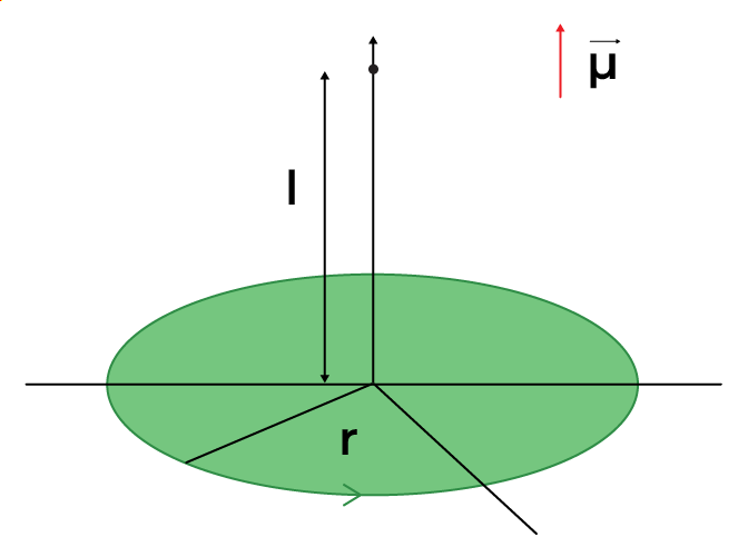

For simplification let us assume that the distance of the point (p) is very far from the current-carrying loop.

as, R<<l
The area of the loop is given as
A = πR2
The magnetic field can be written as

As, μ = iA
The above formula for magnetic field is similar to the Electric dipole field

Solved Problems on Circular Current loop as a Magnetic Dipole
Problem 1: Two wires of the same length are shaped into a square and a circle. If they carry the same current, then the ratio of their magnetic moments is:
Solution:
The magnetic moment of a loop is given by (m) = IA
The wires have the same length,
Perimeter of a square = Circumference of a circle
Therefore, 4a = 2πr
a = πr / 2 …(1)
The magnetic moment of the square loop is given by,
m1 = I(A1)
⇒ m1 = Iπ2r2 / 4 [from equation (1)] …(2)
The magnetic dipole moment of a circular loop is given by,
m2 = I(A2)
m2 = I(πr2) …(3)
From equations (2) and (3), we get
m1 / m2 = π / 4
Problem 2: A circular coil of 300 turns and a diameter of 14 cm carries a current of 15 A. The magnitude of the magnetic moment associated with the loop is going to be
Solution:
Given:
Number of turns (N) = 300
Radius of coil (r) = 14/2 = 7cm = 7 × 10⁻² m
Current in coil (I) = 15A
Magnetic moment (M) = NI(πr2)
M = 300 × 15 × 22/7 × (7 × 10-2)2
M = 69.2 JT-1
Problem 3: A circular coil of 100 turns, each turn of radius 8 cm carries a current of 0.4 A. What is the magnitude of the magnetic field B at the center of the coil?
Solution:
Given:
Number of turns (N) = 100
radius of each turn (r) = 8cm = 8 × 10⁻²m
Current flowing in the coil (I) = 0.4 A
permeability of free space (μ0) = 4π × 10-7 TmA-1
The magnitude of the magnetic field at the center of the coil can be obtained by,
|B| = μ0 2πnI / 4πr
|B| = (4π × 10-7 / 4π) × (2π × 100 × 0.4 / 8 × 10⁻²)
|B| = 3.14 × 10⁻⁴ T
Problem 4: A long straight wire in the horizontal plane carries 50 A in the north-to-south direction. Give the magnitude and direction of B at a point 2.5 m east of the wire.
Solution:
Given:
Current in the wire (I) = 50 A
Distance of a point from the wire (r) = 2.5 m
permeability of free space (μ0) = 4π × 10-7 TmA-1
The magnitude of the magnetic field at a given point can be obtained by,
|B| = μ0 2I / 4πr
|B| = (4π × 10-7 / 4π) × (2 × 50 / 2.5)
|B| = 4 × 10⁻⁶ T
Problem 5: Two very long wires are placed parallel to each other and separated by a distance of 1m apart. If the current in both the wires is 1A, then the force per unit length on both wires will be:
Solution:
Current in both the wires Ia = Ib = 1A
distance (d) = 1m
The force per unit length is given as,
fab = fba = f = μ0IaIb / 2πd —(1)
from equation (1),
f = (μ0×1×1) / (2π×1)
f = μ0/2π × 2/2
f = 2μ0/4π —(2)
we know,
μ0/4π = 10-7 T – m/A —(3)
from equations (2) and (3),
f = 2 × 10⁻⁷ N
FAQs Circular Current Loop as a Magnetic Dipoles
Question 1: What is a magnetic dipole?
Answer:
A magnetic dipole is an object where two opposite magnetic poles (north and south) of equal strength are kept at a very short distance, these dipoles can be bar magnets.
Question 2: State Characteristics of Magnetic Field Lines.
Answer:
Few of the characteristics of magnetic Field Lines are:
- The magnetic field lines form continuous and closed loops.
- Magnetic field lines never intersect each other.
- The strength of the magnetic field in a particular area can be determined by the number of field lines crossing per unit area. The more the number of lines, the more the strength of the magnetic field at that point.
- The tangent drawn from any field line will give the direction of the magnetic field at that point.
Question 3: Define Magnetic Dipole Moment.
Answer:
The magnetic dipole moment is defined as the maximum amount of torque generated by magnetic force on a dipole that arises per unit value of the surrounding magnetic field in a vacuum.
Question 4: What is the difference between Magnetic dipole and Magnetic dipole moment?
Answer:
A magnetic north pole and a magnetic south pole separated by a short distance are termed a magnetic dipole. Magnetic dipole moments have dimensions of current times area of energy divided by magnetic flux density.
Question 5: Define the Magnetic field.
Answer:
The space or region around the current carrying wire or around the magnetic material in which force of magnetism can be experienced by other magnetic material is called magnetic field or magnetic induction by that material.
Question 5: State the formula for the magnetic force between two wires.
Answer:
The formula for magnetic force between two parallel, long and straight current-carrying wires is given by,
Fba = μ0IaIb / (2πd)
Here, Fab is the force per unit length, d is the distance between wires, la and lb are the currents flowing in the first and second wires.
Moving Coil Galvanometer
Hans Christian Oersted discovered in 1820 that a current-carrying conducting wire produces a magnetic field around it. His findings from his experiments are as follows:
- The magnetic compass needle is aligned tangent to an imaginary circle centered on the current-carrying cable.
- When the current is reversed, the needle’s orientation is reversed as well.
- The strength of the current flowing through the wire determines the needle’s deflection.
Magnetic fields mediate a class of physical properties known as magnetism. A magnetic field is created by electric currents and the magnetic moments of elementary particles, which operate on other currents and magnetic moments. Electromagnetism is a multifaceted phenomenon that includes magnetism. The most well-known effects occur in ferromagnetic materials, which are highly attracted to magnetic fields and can be magnetized to become permanent magnets that generate magnetic fields.
What is Torque?
The force that can cause an object to twist along an axis is measured as torque. In linear kinematics, force is what causes an object to accelerate. Torque is also responsible for the angular acceleration. As a result, torque can be defined as the linear force’s rotational equivalent. The axis of rotation is the point at which the item rotates. Torque is the property of a force to turn or twist.
The torque might be static or dynamic. A torque that does not cause an angular acceleration is known as static torque.
e.g.:
- When a person pushes a closed door, the door remains static because it does not rotate despite the force applied.
- Because there is no acceleration, pedaling a bicycle at a steady speed is likewise an example of static torque.
Torque produced on a Rectangular Current loop in a Uniform Magnetic Field
When a rectangular loop with N turns of area A each carries a continuous current I and is put in a uniform magnetic field B so that the loop’s normal to the plane makes an angle with the magnetic field’s direction, the loop experiences a torque whose magnitude is given by:
τ= NIAB sin θ
The magnetic dipole moment of the current loop is defined as,
|m| = NIA
The magnetic dipole moment of a current-carrying loop can be calculated as the product of the loop’s current and total area, i.e.
M = I . (NA)
Due to the current in the loop, the magnetic dipole moment is a vector quantity with a direction parallel to the magnetic field direction.
Moving Coil Galvanometer
A moving coil galvanometer is an instrument for measuring electric currents. It’s a sensitive electromagnetic gadget that can detect extremely low currents, down to a few microamperes.
There are two primary types of moving-coil galvanometers:
- A galvanometer with suspended coils
- A galvanometer with a pivoting coil or a Weston galvanometer
Principle
Magnetic torque is experienced when a current-carrying coil is put in an external magnetic field. The angle through which the coil is deflected due to the magnetic torque effect is proportional to the coil’s current magnitude.
Construction
The moving coil galvanometer is made consisting of a rectangular coil with several turns that are wound on a metallic frame and is usually constructed of thinly insulated or fine copper wire. The coil rotates freely around a fixed axis. The coil is suspended in a uniform radial magnetic field using a phosphor-bronze strip coupled to a moveable torsion head.
Conductivity and a low torsional constant are two important qualities of the material used to suspend the coil. To boost the strength of the magnetic field and make it radial, a cylindrical soft iron core is symmetrically positioned inside the coil. The coil’s lower half is connected to a phosphor-bronze spring with a modest number of turns. The spring’s other end is attached to binding screws.
The spring is employed to generate a counter torque that serves to balance the magnetic torque and produce a consistent angular deflection. The deflection of the coil is measured using a plane mirror attached to the suspension wire, as well as a lamp and scale arrangement. The scale’s zero points are in the middle.
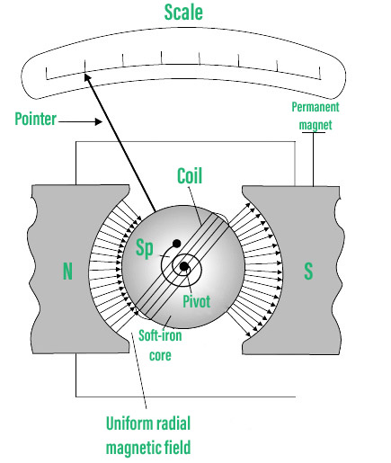
Pictorial representation of Galvanometer
Working
Allow me to pass through a rectangular coil with n turns and an area of A in cross-section. When the coil is placed in a uniform radial magnetic field B, it experiences a torque. Consider a rectangular coil with a length of l and a width of b with a single turn ABCD. The coil is suspended in a magnetic field of strength B, with the plane of the coil parallel to the field. The sides AB and DC are not subjected to any magnetic field’s effective force because they are parallel to the field’s direction.
The perpendicular to the field’s direction sides AD and BC are subjected to an effective force F, which is given by,
F = BI
We may deduce that the forces acting on AD and BC are in opposite directions using Fleming’s left-hand rule. When equal and opposite forces F, known as the pair, act on the coil, a torque is produced. The coil deflects as a result of the torque.
We know that,
Torque (τ) = force x perpendicular distance between the forces
or
τ = F × b
Using the value of F that we already know as a substitute,
Torque τ acting on single-loop ABCD of the coil = BI × b
where l × b is the area A of the coil,
Hence the torque acting on n turns of the coil is given by,
τ = n I A B
The coil rotates as a result of the magnetic torque, and the phosphor bronze strip twists. The spring S linked to the coil, in turn, provides a counter torque or restoring torque k, resulting in a constant angular deflection.
Under equilibrium condition:
kθ = nIAB
The torsional constant of the spring is denoted by the letter k (restoring couple per unit twist). The deflection or twist is measured by a pointer attached to the suspension wire that indicates a value on a scale.
θ = (nAB / k) I
Therefore,
θ ∝ I
For a given galvanometer, the quantity nAB / k is a constant. As a result, it is clear that the deflection of the galvanometer is proportional to the current flowing through it.
Sensitivity Of Moving Coil Galvanometer
The ratio of change in deflection of the galvanometer to change in current in the coil is the broad definition of sensitivity experienced by a moving coil galvanometer.
S = dθ/ dI
If a galvanometer shows a larger deflection for a modest amount of current, it has a higher sensitivity. Current sensitivity and voltage sensitivity are the two types of sensitivity.
- Current sensitivity: The deflection (θ) per unit current (I) is known as current sensitivity θ/I
θ/I = nAB/k
- Voltage sensitivity: Voltage sensitivity θ/V is the amount of deflection (θ) per unit voltage(V)
θ/V= (nAB/Vk) I
The effective resistance in the circuit is denoted by the letter R. It’s worth remembering that voltage sensitivity is equal to current sensitivity/coil resistance. As a result, assuming R remains constant, voltage sensitivity ∝ current sensitivity.
The figure of Merit of a Galvanometer: It’s the proportion of the full-scale deflection current of the instrument to the number of graduations on the scale. It’s also the reciprocal of the current sensitivity of a galvanometer.
Factors affecting Sensitivity of a Galvanometer:
- The number of turns in the coil N and the coil’s area A.
- The strength of the magnetic field B.
- k/nAB is the magnitude of the pair per unit twist.
Applications of Galvanometer
Because the moving coil galvanometer is such a sensitive instrument, it may be used to detect the presence of current in any circuit. When a galvanometer is used in a Wheatstone’s bridge circuit, the pointer in the galvanometer exhibits no deflection, indicating that no current is flowing through the device. Depending on the direction of the current, the pointer deflects to the left or right.
By connecting it in parallel to low resistance, the galvanometer can be used to measure:
- The value of current in the circuit.
- The voltage can be increased by connecting it in series with a high resistance resistor.
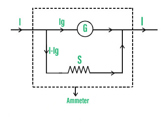
Conversion of Galvanometer to Ammeter
By connecting a galvanometer in parallel with a low resistance known as shunt resistance, a galvanometer can be transformed into an ammeter. Depending on the ammeter’s range, a suitable shunt resistance is selected.
Let’s now consider Rg as the Resistance of the galvanometer, G as Galvanometer coil, I represents the total current passing through the circuit, Ig represents the total current passing through the galvanometer which corresponds to full-scale reading, and Rs shows the value of shunt resistance.
The current via the shunt resistance, when current Ig passes through the galvanometer is given by,
Is = I – Ig
Due to the parallel nature of their connection, the voltages across the galvanometer and shunt resistance are equal.
Therefore,
Rg × Ig = (I – Ig) × Rs
Galvanometer to Voltmeter
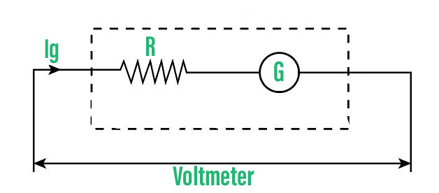
Conversion of Galvanometer to Voltmeter
By putting a galvanometer in series with large resistance, it can be transformed into a voltmeter. Depending on the voltmeter’s range, a suitable high resistance is selected.
Let’s now consider Rg as the Resistance of the galvanometer, G as Galvanometer coil, I represents the total current passing through the circuit, Ig represents the total current passing through the galvanometer which corresponds to full-scale reading, and V shows the voltage drop across the series connection of galvanometer and high resistance.
The voltage drop across the branch ab is given by when current Ig travels through the series combination of the galvanometer and the high resistance R.
V = Rg × Ig + R × Ig
Galvanometer to voltmeter
Advantages of a Moving Coil Galvanometer are:
- Provides high Sensitivity.
- Stray magnetic fields have little effect on it.
- It has a high torque-to-weight ratio.
- High precision and dependability.
Disadvantages of a Moving Coil Galvanometer are:
- Only direct currents can be measured using it.
- Errors develop as a result of causes such as instrument aging, permanent magnets, and mechanical stress damage to the spring.
Sample Problems
Problem 1: For a current of 4mA, a galvanometer coil with a resistance of 40 shows full range deflection. How can this galvanometer be transformed into a 0-12 V voltmeter?
Solution:
As we know that V = IG (RG + R)
R = V/ IG – RG
= (12/ (4×10⁻³)) – 40
R = 2960 Ω
Problem 2: What is the purpose of putting a soft iron cylindrical core inside the moving coil galvanometer?
Solution:
The inside of the galvanometer has a cylindrical soft iron core that boosts the magnetic field strength and so improves the instrument’s sensitivity. It also makes the magnetic field radial, ensuring that the angle between the coil’s plane and the magnetic lines of force is always zero during rotation.
Problem 3: With a resistance of 0.1 Ω, a moving coil galvanometer of resistance of 100 Ω is used as an ammeter. The galvanometer’s maximum deflection current is 100 μA. Find the current in the circuit that causes the ammeter to deflect the most.
Solution:
It is given that, Rg =100Ω , Rs= 0.1Ω, Ig =100μA
We know that, Rg x Ig= (I- Ig) x Rs
Therefore I = (Rg x Ig+ Ig x Rs)/ Rs
I= (1+Rg/ Rs) x Ig
Substituting the given values, we get I= 100.1mA
Problem 4: What is the principle of Moving coil galvanometer?
Solution:
Magnetic torque is experienced when a current-carrying coil is put in an external magnetic field. The angle through which the coil is deflected due to the magnetic torque effect is proportional to the coil’s current magnitude.
Problem 5: Write Advantages of moving coil galvanometer
Solution:
- Sensitivity is high.
- Stray magnetic fields have little effect on it.
- It has a high torque-to-weight ratio.
- High precision and dependability.
0 Comments