
CHAPTER 10 - WAVE OPTICS
Huygen’s Wave Theory
Christiaan Huygens proposed the Huygens principle. In 1678, he changed the way we think about light and its properties. You’ve probably heard of the rectilinear theory of light, which states that light travels in straight lines. One of the most important ways for examining various optical phenomena is the Huygens principle. The principle is an analysis method that can be used to solve wave propagation problems in the far-field limit, near-field diffraction, and reflection.
When you open a window in a room, light comes in through it and spreads around the space. Do you know why this happens? This is due to the fact that light has a wave character and spreads around the room in all directions. Let’s look at Huygen’s Principle to get a better understanding of this.
Huygen’s Principle
Every point on a wavefront is a source of spherical wavelets that expand out at the speed of light in the forward direction. The wavefront is formed by the sum of these spherical wavelets.”
This explanation, however, does not explain why refraction took happened in the first place. Second, it was unable to explain how light transfers energy along its path. The Huygens Principle, also known as the Huygens–Fresnel Principle, emphasises the wave propagation behaviour as follows:
- Secondary sources generate wavelets that are comparable to the original source’s wavelets.
- The new wavefront is determined by the common tangent on the wavelets in the forward direction at any given time.
- The total of the spherical wavelets is the wavefront.
Wavefront and Wave Normal
Consider a point source of light ‘S’ in ‘air.’ The light waves emitted by this source go in all directions. If ‘c’ is the velocity of light in air, each wave will travel ‘ct’ in time t and reach the surface of a sphere with radius ‘ct’. With the source ‘S’ as its focal point. This type of surface is known as a spherical wave surface.
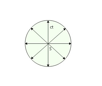
Wave surface
A wavefront is a locus of all the points of medium to which waves arrive simultaneously so that all the points are in the same phase (see image below), for example, light emitted by a bulb at a limited distance. A plane wavefront emerges from a convex lens when a point source of light is positioned at its focal point. In addition, if the spherical wavefront is sufficiently big, a tiny portion of the surface can be considered a plane wavefront. For example, wavefronts are caused by sunlight. A linear source (such as a slit) produces a cylindrical wavefront. For example, light is emitted by a fluorescent tube.
Wavefront and Wavenormal
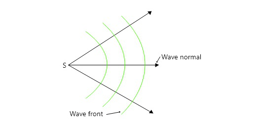
A wave normal is a perpendicular drawn to the surface of a wavefront in the direction of light propagation. A wavefront, in other words, transports light energy perpendicular to the surface.
Wave Normal
Types of wavefronts – There are three types of wavefronts, that are
- Spherical wavefront: Consider the ‘S’ point source of light. Light waves generated by S can move in any direction. If c is the speed of light, then each wave will reach the surface of a sphere with radius ct and centre S after time t. This spherical surface is known as the spherical wavefront at time t, and it is derived from a finite-distance point source. For example, consider the light emitted by a bulb at a limited distance.
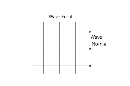
- Plane wavefront: The spherical wavefront is so enormous at a very vast distance from the point source that a tiny portion of it may be considered a plane wavefront. It is derived from an infinitely distant point source. As an example, consider the wavefront caused by sunlight.
- Cylindrical wavefront: If the source of light is linear i.e., a slit, then we get a cylindrical wavefront. It is obtained from a linear source kept at a finite distance. For example, light is emitted by a fluorescent tube.
Huygen’s Construction of a spherical wavefront
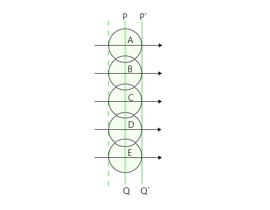
Let PQ be a cross-section of a spherical wavefront due to a point source(S), at any instant. This can be called as primary wavefront. Now consider points A, B, C, D, E on PQ. They act as secondary sources and send out secondary wavelets as per Huygens’ principle.
If c is the speed of light in the isotropic medium, in time t, each wave will describe a distance ‘ct’. With A, B, C, D, E as centres of circles, each radius ct will be traced. Each circle will represent a secondary wavefront.
The common tangential surface (envelope) P’Q’ drawn to these secondary wavefronts represents the (new) position of the wavefront after time ‘t’. The secondary waves moving in the backward direction do not exist.
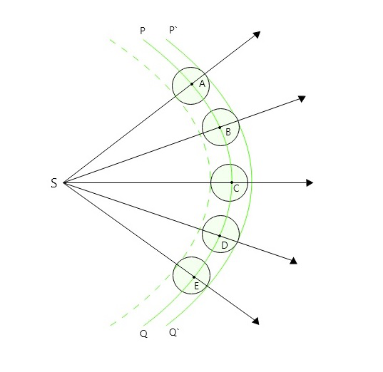
Huygen’s Spherical Wavefront
Huygen’s Construction of a plane wavefront
Let PQ be a plane wavefront perpendicular to the plane of the paper due to a point source(S), at any instant and at a very large distance, This can be called a primary wavefront. Now consider points A, B, C, D on PQ. They act as secondary Huygens’ sources and send out secondary wavelets as per Huygens’ principle.
If ‘c’ is the speed of light in the isotropic medium, in time ‘t’, each wave will describe a distance ‘ct’. With A, B, C, D as centres, spheres each of radius ‘ct will be traced, each sphere will represent a secondary wavefront. The common tangential surface(envelope) i.e.P’Q’ drawn to these secondary wavefronts represents the new position for the wavefront after time ‘t’.
The secondary waves moving in the backward direction do not exist and therefore they are shown with dotted lines.
Huygen’s plane wavefront
Advantages of Huygen’s Principle
- It could explain the laws of refraction, interference, reflection, diffraction, etc.
- The wave theory predicted that the speed of light in an optically denser medium is less than that in an optically rarer medium as was experimentally proved by Focault.
Disadvantages of Huygen’s Principle
- It could not explain the rectilinear propagation of light. The Rectilinear Propagation of Light describes that Light travels in a Straight Line.
- It could not explain the phenomenon of polarization of light and phenomena like the Raman effect, Compton effect and Photoelectric effect. It was modified later that light is a transverse wave.
- Huygens`assumed the presence of a hypothetical medium [Ether]. The properties of hypothetical ether were studied further by Michelson and Morley with their apparatus based on the principles of interference of light beams. The experiment concluded that there is no ether drag when the earth moved through it. This and other experiments proved that ether does not exist.
Sample Questions
Question 1: State any three assumptions of Huygens wave theory of light?
Answer:
Assumptions of Huygens wave theory are as below:
- Light is propagated in form of longitudinal waves
- Different colors of light are due to different wavelengths of light waves.
- We feel sensation when light waves enter our eyes.
Question 2: State merits and Demerits of Huygens wave theory of light
Answer:
Merits:
- This theory could explain the laws of reflection, refraction, diffraction, interference, etc.
- According to this theory, the speed of light in a denser medium is less than that in a rarer medium. [This conclusion is in perfect agreement with the experimental results.]
Demerits:
- His theory could not explain rectilinear propagation of light.
- Huygens` assumed the presence of the hypothetical medium, ether.
- Experimentally it was proved that ether does not exist.
- This theory fails to explain the polarization of light phenomenon like Photoelectric effect, Compton effect and Raman effect.
Question 3: Define Wavefront and Wave Normal.
Answer:
Wavefront: A locus containing all of the points of medium to which waves arrive at the same time, so that all of the points are in the same phase.
Wave normal: A wave normal is a perpendicular drawn to the surface of a wavefront at any point along the wavefront in the direction of light propagation.
Question 4: Give the difference between Plane and Spherical wavefront?
Answer:
The difference between Plane and Spherical wavefront are:
Plane Wavefront
Spherical Wavefront
It is obtained from a point source of light kept at infinite distance. It is obtained from a point source of light kept at finite distance. The rays of light are parallel to each other. The rays of light are convergent or divergent in nature. It is plane in shape It is spherical in shape Radius of curvature is infinite Radius of curvature is finite Example: Wavefront due to sunlight. Example: light emitted by a bulb at a finite distance.
Question 5: Explain how cylindrical wavefronts are produced and give an example?
Answer:
Cylindrical wavefront: In a cylindrical wavefront, all points are equidistant from the linear source and lie on the cylinder’s surface.
- If the source of light is linear i.e., a slit, then we get a cylindrical wavefront.
- It is obtained from linear source kept at finite distance.
Example: A little rectangular slit. A cylindrical wavefront is produced when light is transmitted through a fine rectangular slit. .
Young’s Double Slit Experiment
Optics is the part of material science that concentrates on the conduct and properties of light, incorporating its connections with issues and the development of instruments that utilise or recognize it. Optics as a rule depicts the conduct of apparent, bright, and infrared light. Since light is an electromagnetic wave, different types of electromagnetic radiation, for example, X-beams, microwaves, and radio waves show comparative properties. Most optical marvels can be represented by utilizing the traditional electromagnetic portrayal of light.
Complete electromagnetic depictions of light are, in any case, frequently hard to apply practically speaking. Down to earth optics is typically done utilizing worked on models. The most widely recognized of these, mathematical optics, regards light as an assortment of beams that move in straight lines and curve when they go through or reflect from surfaces. Actual optics is a more thorough model of light, which incorporates wave impacts, for example, diffraction and obstruction that can’t be represented in mathematical optics. By and large, the beam based model of light was grown first, trailed by the wave model of light. Progress in the electromagnetic hypothesis in the nineteenth century prompted the disclosure that light waves were indeed electromagnetic radiation.
Young’s Double Slit Experiment
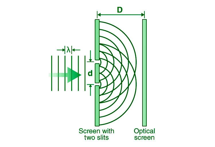
Young’s double-slit experiment employs two coherent light sources separated by a modest distance, generally a few orders of magnitude larger than the wavelength of light.
Young’s double-slit experiment aided in the understanding of lightwave theory. The slits are separated by a large distance ‘D’ from a screen or photodetector. Young’s original double-slit experiment employed diffracted light from a single source that was then transmitted through two additional slits to serve as coherent sources. In today’s investigations, lasers are frequently employed as coherent sources.
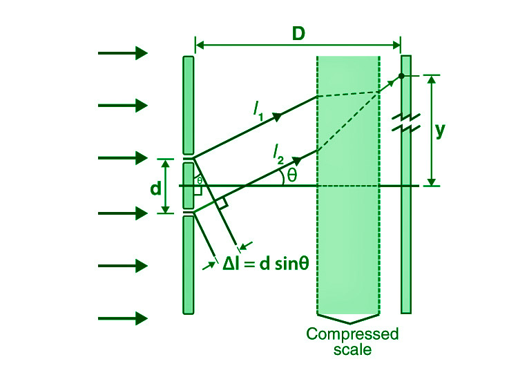
Each source may be thought of as a coherent lightwave source. The waves travel lengths l1 and l2 to generate a path difference of l at any place on the screen at a distance ‘y’ from the centre. At the sources, the point roughly subtends an angle of (since the distance D is large there is only a very small difference of the angles subtended at sources).
Derivation for Young’s Double Slit Experiment
Consider a monochromatic light source ‘S’ that is kept a long way from two slits s1 and s2. S is in the same plane as s1 and s2. Because both s1 and s2 are drawn from S, they act as two consistent sources.
The light travels through these slits and lands on a screen that is positioned at a distance ‘D’ from the apertures s1 and s2. The distance between two slits is denoted by the letter ‘d.’
If s1 is open and s2 is closed, the screen opposite s1 is darkened, leaving just the screen opposite s2 lit. Only when both slits s1 and s2 are open can interference patterns form.
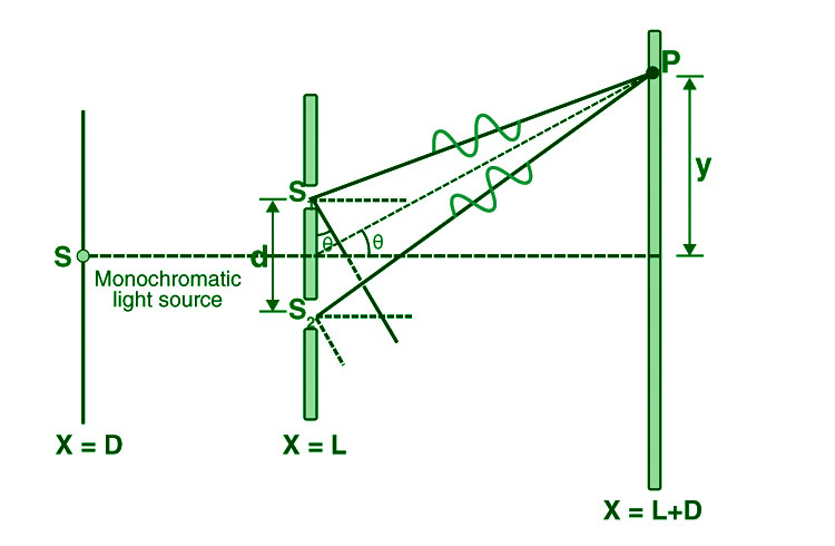
At the point when the cut partition (d) and the screen distance (D) are kept unaltered, to arrive at P the light waves from s1 and s2 should travel various distances. It suggests that there is a way contrast in Young’s twofold cut test between the two light waves from s1 and s2.
Approximations in Young’s twofold cut analysis-
Guess 1: D > d
Since D > d, the two light beams are thought to be equal.
Guess 2: d/λ >> 1
Often, d is a small amount of a millimeter and λ is a negligible portion of a micrometer for noticeable light.
Under these conditions θ is little, consequently, we can utilize the estimate,
sin θ = tan θ ≈ θ = λ/d
∴ the path difference,
Δz = λ/d
This is the path difference between two waves meeting at a point on the screen. Because of this path difference in Young’s twofold cut investigation, a few focuses on the screen are brilliant and a few focuses are dull.
Position of Fringes In Young’s Double Slit Experiment
- Position of Bright Fringes
For maximum intensity or bright fringe to be formed at P
Path difference, Δz = nλ (n = 0, ±1, ±2, . . . .)
i.e.
xd/D = nλ
or
x = nλD/d
The distance of the nth bright fringe from the centre is
xn = nλD/d
Similarly, the distance of the (n-1)th bright fringe from the centre is
x(n-1) = (n -1)λD/d
Fringe width, β = x n – x (n-1) = nλD/d – (n -1)λD/d = λD/d
(n = 0, ±1, ±2, . . . .)
- Position of Dark Fringes
For minimum intensity or dark fringe to be formed at P,
Path difference, Δz = (2n + 1) (λ/2) (n = 0, ±1, ±2, . . . .)
i.e.
x = (2n +1)λD/2d
The distance of the nth dark fringe from the centre is
xn = (2n+1)λD/2d
Similarly, the distance of the (n-1)th bright fringe from the centre is
x(n-1)= (2(n-1) +1)λD/2d
Fringe width, β = x n – x (n-1) = (2n + 1) λD/2d – (2(n -1) + 1)λD/2d = λD/d
(n = 0, ±1, ±2, . . . .)
Fringe Width
The fringe width is the distance between two consecutive bright (or dark) fringes.
β = λD/d
When Young’s double-slit experiment equipment is submerged in a liquid with a refractive index of (μ), the wavelength of light and the fringe width both fall by ” times.
β 1= β/μ
When white light is utilised instead of monochromatic light, coloured fringes appear on the screen, with red fringes being bigger than violet fringes.
Maximum Order of Interference Fringes
On the screen, the position of nth order maximum is,
γ = nλD/d
where n=0, ±1, ±2, …
However, because the 2nd approximation would be violated, ‘n’ values cannot take infinitely high values. i.e. θ is small (or) y << D.
⇒ γ/D = nλ/d <<1
As a result, the above formula for interference maxima can be used n<< d/λ. When the value of ‘n’ equals that of d/λ, the path difference can no longer be calculated as dγ/D.
Hence for maxima, path difference = nλ
⇒ dsinθ = nλ
or
n = dsinθ/λ
and
nmax= d/λ
The above represents the box function or greatest integer function. Similarly, the highest order of interference minima is given by,
nmin=[d/λ+1/2]
Shape of Interference Fringes in YDSE
The route difference between the two slits is represented by the YDSE diagram.
s2p−s1p≈dsinθ (constant)
The preceding equation depicts a hyperbola with two foci denoted by the letters s1 and s2.
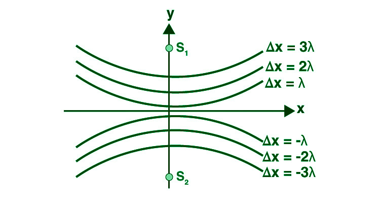
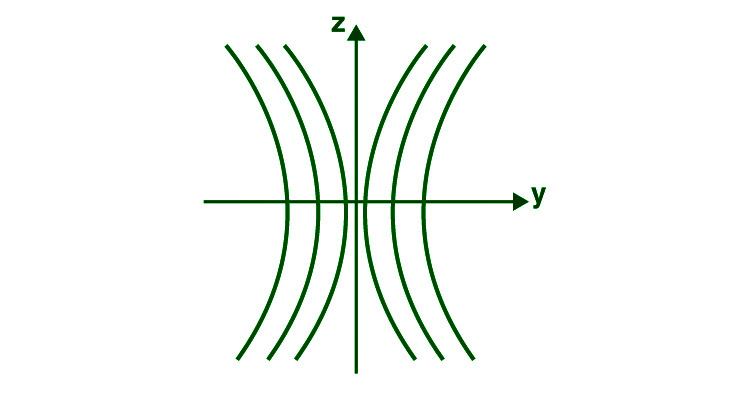
When we rotate a hyperbola on the axis s1s2, we obtain an interference pattern on the screen that is a segment of a hyperbola. Fringes are hyperbolic with a straight middle portion of the screen is in the yz plane.
Intensity of Fringes in YDSE
The resulting intensity at location p for two coherent sources s1 and s2 is given by
I = I1 + I2 + 2 √(I1 . I2) cos φ
Putting, I1 = I2 = I0 (Since, d<<<D).
I = I0 + I0 + 2 √(I0.I0) cos φ
= 2I0 + 2 (I0) cos φ
= 2I0 (1 + cos φ)
= 4I0cos2(ϕ/2)
Constructive and Destructive Interference
The path difference must be an integral multiple of the wavelength for constructive interference to occur. As a result, if a brilliant fringe is at ‘y,’
nλ = y d/D
where n = ±0,1,2,3…..
The centre brilliant fringe is represented by the 0th fringe. Similarly, in Young’s double-slit experiment, the expression for a black fringe may be obtained by setting the path difference to:
Δl = (2n+1)λ/2
This simplifies to,
(2n+1)λ/2 = y d/D
or
y = (2n+1)λD/2d
Young’s double-slit experiment was a breakthrough point in science because it proved beyond a shadow of a doubt that light behaved like a wave. Later, the Double Slit Experiment was repeated using electrons, and to everyone’s amazement, the pattern produced was nearly identical to that seen with light. This would forever alter our perceptions of matter and particles, requiring us to believe that matter, like light, acts like a wave.
Sample Questions
Question 1: In Young’s double-slit experiment, the ratio of brightness at minima to peaks is 9:25. Calculate the ratio of the two-slit widths.
Answer:
Imax/Imin = (a1+a2)2/(a1-a2)2
= 9/25
Solving, a1/a2 = 4/1
Therefore, Ratio of slit width , w1/w2 = a12/a22=16.
Question 2: The distance between the slits in a double-slit experiment is 3 mm, and the slits are 2 m apart from the screen. On the screen, two interference patterns can be observed, one caused by light with a wavelength of 480 nm and the other by light with a wavelength of 600 nm. What is the distance between the fifth-order brilliant fringes of the two interference patterns on the screen?
Answer:
Separation is given by,
y= nλD/d
where,
d = 3 mm = 3 × 10 −3 m
D = 2 m
λ1 = 480 nm = 480×10 −9 m
λ2 = 600 nm = 600×10 −9 m
n1=n2=5
So,
y1= nλ1D/d
y1= 5×480×10 −9×2 / 3×10 −3
y1=1.6×10⁻³m
Also,
y2= nλ2D /d
y2= 5×600×10−9×2 / 3×10⁻³
y2=2×10⁻³m
As , y2 > y 1
y 2 − y1 = 2×10 −3−1.6×10 −3
= 4×10 −4 m
Therefore the separation on the screen between the fifth order bright fringes of the two interference patterns is 4×10⁻⁴ m.
Question 3: The widths of two slits in Young’s experiment are 1: 25. The intensity ratio at the interference pattern’s peaks and minima, Imax/Imin is
Answer:
Intensity is proportional to width of the slit. thus, I1/I2
= 1/25
or a1/a2 = 1/5
Imax/Imin = (a1+a2)2/(a1-a2)2
= (a1+5a1)2/(a1-5a1)2
= 36/16
= 9/4
Question 4: Two lucid point sources S1 and S2 vibrating in stage radiate light of frequency λ. The division between the sources is 2λ. Consider a line going through S2 and opposite to the line S1S2. What is the littlest separation from S2 where at least power happens?
Answer:
For minimum intensity of light, path difference must be equal to path difference for dark e.g Δx=λ/2,3λ/2,5λ/2
Consider Δx=(2λ−λ/2)=3λ/2
Now, path difference=S1P−S2P
Δx= √(4λ2+x2)−x
3λ/2+x= √4λ 2+x 2
Taking square on both sides,
9λ2/4+x 2+3λx=4λ 2+x 2
3λx=4λ2−9λ2/4
x=7λ/12
The smallest distance from S2 where a minimum of intensity occurs is 7λ/12
Question 5: A glass lens is coated with a thin layer having a refractive index of 1.50. The glass has a refractive index of 1.60. What is the thinnest film coating that will reflect 546 nm light extremely strongly (constructive thin film interference)?
Answer:
Light is entering in a medium of higher refractive index (n2=1.60) from a medium of lower index (n1=1.50), therefore net path difference in the reflected rays from the two interfaces will be equal to 2t (where t is thickness of thin film) , because when light goes from air to thin film path shift in reflected ray =λ’/2, when light goes from thin film to glass path shift in reflected ray =λ’/2+2t
for constructive interference,
2t=mλ’ or 2t=mλ/n1
where λ’= wavelength in thin film ,
λ=546nm(given) wavelength in vacuum ,
for thinnest coating , m=0(minimum) ,
therefore, tmin = λ/2n1
= 546/(2×1.50) =182nm
Question 6: The initial minimum of the interference pattern of monochromatic light of wavelength e occurs at an angle of λ/a for a single slit of width “a.” We find a maximum for two thin slits separated by a distance “a” at the same angle of λ/a. Explain.
Answer:
Width of the slit is a.
The path difference between two secondary wavelets is given by,
Nλ=asinθ
Since, θ is very small, sinθ=θ
So, for the first order diffraction n=1, the angle is λ/a
Now, we know that θ must be very small θ=0 (nearly) because of which the diffraction pattern is minimum.
Now for interference case, for two interfering waves of intensity l1 and l2
we must have two slits separated by a distance.
We have the resultant intensity, l=l1+l−2+ 2 √l1l 2cosθ
Since, θ=0 (nearly) corresponding to angle λ/a, so cosθ=1 (nearly)
So,
l=l1+l2 +2 √ l1l 2cosθ
l=l1+l2+2 √ l1l2cos0
l=l1+l2+2 √ l1l2
We see the resultant intensity is sum of the two intensities, so there is a maxima corresponding to the angle λ/a
This is why at the same angle λ/a we get a maximum for two narrow slits separated by a distance a.
Question 7: The highest and minimum intensities in an interference pattern created by two coherent sources of light have a 9:1 ratio. what is the brightness of the light used?
Answer:
Imax /Imin = (a1+a2)2 / (a1-a2)2
9/1 = (a1+a2)2 / (a1-a2)2
a1/a2 = 2/1
a12 / a22 = l1 / l2
= 4/1
Diffraction of light
Diffraction is a phenomenon shown by light. When the wave of light interacts with the particle in the atmosphere it bends at the corners and scatters in the area to illuminate the whole area, this phenomenon is called the Diffraction of light. It is a property of light which is used to explain various phenomena observed in our daily life.
Let’s learn about diffraction in detail in this article.
Table of Content
What is Diffraction?
Bending of light around corners such that it spreads out and illuminates’ regions is known as diffraction.
Diffraction can be observed easily when we replace the double slit of the young double slit experiment with a single narrow slit. As the light passes this narrow slit a bright pattern at the centre is observed.
The diffraction phenomenon is very similar to the interference phenomenon and they both happen simultaneously. Generally, it’s difficult to distinguish between diffraction and interference since they both happen at the same time. Diffraction is observed when light is diffracted from water droplets in the clouds and we see shades of blue, pink, purple, and green in clouds.
Diffraction Examples
Examples of diffraction can easily be observed in our daily life, some of the most common ones are, the silver lining seen on the edges of the clouds because of the diffraction of light by water droplets.
The intensity of the diffraction of light varies with the wavelength of the light used where the light with a higher wavelength diffracts in comparison to light with a smaller wavelength.
Types of Diffraction
We can categorise diffraction into two categories that are,
- Fraunhofer Diffraction
- Fresnel Diffraction
Fraunhofer Diffraction
- When all the light rays passing through the narrow slit are parallel to each other then the diffraction which occurs is called Fraunhofer Diffraction.
- This diffraction is achieved by placing the light source far away from the narrow slit.
- The screen and the source are at an infinite distance from each other in this type of diffraction. Fraunhofer Diffraction uses a convex lens to produce a diffracting pattern.
Fresnel Diffraction
- If the light source and screen at which the diffraction pattern is obtained are at finite distances then the diffraction is called Fresnel Diffraction.
- In Fresnel Diffraction, the shapes obtained from the incident wavefronts are spherical. In this type of diffraction, a convex lens is not required.
Single Slit Diffraction
We may see the bending phenomena of light, or diffraction, in the single-slit diffraction experiment, which causes light from a coherent source to interfere with itself and form a distinct pattern on the screen termed the diffraction pattern. When the sources are tiny enough to be comparable in size to the wavelength of light, diffraction occurs. This impact may be seen in the diagram below,
.png)
Single Slit Diffraction Formula
Denote the slit width as ‘a’, and the distance between the slit and the screen as D such that a<<<D.
.png)
The angular location of any point on the screen will be determined by measuring from the slit centre, which splits the slit by a ⁄ 2 lengths. To explain the pattern, we’ll look at the state of black fringes first. Let us also split the slit into equal-width zones a ⁄ 2. Let’s take a look at a pair of rays that come from a ⁄ 2 distances apart, as illustrated below.
.png)
The top two rays indicate the following route difference:
Δ L = (a ⁄ 2) sinθ
Note: Remember that this is only a viable computation if D is really large.
Any number of ray pairs that start at a distance of a ⁄ 2 from one another, such as the bottom two rays in the diagram, can be considered. Any arbitrary pair of rays separated by a ⁄ 2 can be taken into account. In a minute, we’ll discover how important this method is.
The path difference must create destructive interference for a dark fringe; the path difference must be out of phase by λ ⁄ 2. (λ represents the wavelength)
For the first fringe,
Δ L = λ ⁄ 2 = a ⁄ 2 sinθ
λ = a sinθ
There is another beam at a distance of a ⁄ 2 that can create destructive interference for a ray coming from any point in the slit. As each ray originating from a point has a counterpart that produces destructive interference, there is destructive interference at θ = sin−1(λ ⁄ a). As a result, a dark fringe is created.
We may divide the slit into four equal portions of a ⁄ 4 and use the same rationale for the next fringe. As a result, for the second minima,
λ ⁄ 2 = a ⁄ 4 sinθ
2λ = a sinθ
Similarly, we may divide the slit into 2n parts for the nth fringe and utilise the following condition:
λ ⁄ 2 = a ⁄ 2n sinθ
n λ = a sinθ
Central Maximum
The maxima are located between the minima, and the width of the central maximum is equal to the distance between the 1st order minima on both sides of the screen.
The position of the minima determined by y (as measured from the screen’s centre) is,
tanθ ≈ θ ≈ y ⁄ D
For small θ,
sinθ ≈ θ
λ = a sinθ ≈ a θ
Angular width,
θ = y/D = λa
Central maximum,
y = λ D a
The centre maximum’s width is just twice this amount.
Width of central maximum = 2λ D a
Angular width of central maximum = 2θ = 2λ a
Resolving Power
- The resolving power of an optical instrument is defined as the capacity of the instrument to distinguish between two objects that are close together and produce distinct images of the two objects.
- In other words, resolving power changes in inverse proportion to the distance between the two objects to be resolved when viewed from an optical instrument. The images of two close-lying objects appear distinct and separate when viewed from the device.
- When a telescope is used to view two stars located close to each other; the telescope’s resolving power will depend on its capacity to resolve the images of the two stars.
- The resolving power of a lens used in a telescope can be determined by its ability to differentiate two lines or points in an object.
Check: Diffraction Grating Formula
Rayleigh’s Criterion
The minimum distances between images must be such that the central maximum of the first image lies on the first minimum of the second and vice versa. Such an image viewed from an optical device is calculated using Rayleigh’s criterion.
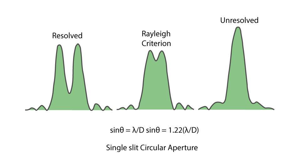
When two objects placed at a distance from each other are separated by an angular separation θ, the diffraction patterns of the two objects will overlap each other. They would appear as one when the two central maxima overlap.
This defines Rayleigh’s resolution criterion. It can be shown that, for a circular aperture of a given diameter, the first minimum in the diffraction pattern occurs at,
θ = 1.22(λ/D)
where,
θ is the angular separation measured in radians
λ is the wavelength of light
D is the diameter of the aperture
What Is the Difference Between Diffraction and Scattering?
The terms diffraction and scattering are often used interchangeably and are considered to be almost synonymous. Diffraction describes a specialized case of light scattering in which an object with regularly repeating features (such as a diffraction grating) produces an orderly diffraction of light in a diffraction pattern. In the real world, most objects are very complex in shape and should be considered to be composed of many individual diffraction features that can collectively produce a random scattering of light.
Read More:
Conclusion of Diffraction of Light
Light diffraction shows how light waves bend and spread when they come into contact with objects or squeeze through narrow spaces. This phenomena is important for many optical applications, such as developing sophisticated optical systems like diffraction gratings or producing rainbows. Knowing diffraction allows for the creation of cutting-edge spectroscopy, microscopy, and telecommunications technologies.
Diffraction of Light – FAQs
What is meant by the diffraction of light?
The phenomenon of bending of light around the edge of the particle is called the diffraction of light.
What is the essential condition for the diffraction of light to occur?
The essential condition for the diffraction of light to occur is the length of the obstacle must be comparable to the wavelength of light.
What is the Phase Difference?
The difference in the phase angle of the two waves is called the phase difference whereas the difference in the path covered by the two waves is called the path difference.,
What is the Condition for Constructive Interference?
If the phase difference between two certain waves is an even multiple of π then constructive interference occurs, also path difference must be an integral multiple of the wavelength.
What is the condition for destructive interference?
If the phase difference between two certain waves is an odd multiple of π then destructive interference occurs.
What is Total Internal Reflection?
When a light ray goes from a denser medium to a rarer medium at an angle greater than the critical angle it gets reflected instead of being refracted this phenomenon is called Total Internal Reflection.
What is the Formula for the Width of the Central Maxima?
The Formula for the Width of the Central Maxima is,
θ = 2λa
Polarization of Light
Polarization of Light: If you were to leave your house on a hot, sunny day, you would undoubtedly wear sunglasses. This is because the light emitted by the sun is unpolarized light and the sunglasses we wear transform the unpolarized light. Polarized light is light in which the electric field vector of the light is in the same phase and is perpendicular to the propagation of the light wave. The process of converting unpolarized light into polarized light is called polarization.
In this article, we will learn about the Polarization of light, types of polarization, Polarization of Light properties, and others in detail.

Table of Content
- What is the Polarization of Light?
- Transverse Waves and Longitudinal Waves
- Polarized Light and Unpolarized Light
- Types of Polarization of Light
- Methods Used in Polarization of Light
- Polarization by Transmission (Polaroids)
- Polarization by Scattering
- Polarization by Reflection and Refraction
- How do Transverse Waves exhibit Polarization?
- Brewster’s Law
- Applications of Polarization of Light
What is the Polarization of Light?
Polarization is a phenomenon induced by the wave nature of electromagnetic radiation, according to physics. Sunlight is an example of an electromagnetic wave since it travels through the vacuum to reach the Earth. Because an electric field interacts with a magnetic field, these waves are known as electromagnetic waves.
Polarization is the process of converting non-polarized light into polarised light. The light in which particles vibrate in all various planes is known as unpolarised light.
Polarization of Light Definition
Polarization of light refers to the phenomenon in which waves of light or electromagnetic radiation are restricted to vibrate in a single direction.
Transverse Waves and Longitudinal Waves
Two types of waves are involved in this phenomenon. These are:
- Transverse Waves: The waves in which the movement of the particles is perpendicular to the wave’s motion direction. For example, when you throw a stone, it creates ripples in the water and sound waves moving across the air.
- Longitudinal Waves: These occur when the medium’s particles move in the same direction as the waves.
The combination of electric and magnetic forces traveling across space is known as light. A light wave’s electric and magnetic vibrations are perpendicular to each other. The magnetic field travels in one direction and the electric field in the other, but they are always perpendicular. So we have an electric field in one plane, a magnetic field perpendicular to it, and a travel direction that is perpendicular to both. Electric and magnetic vibrations can happen in a variety of planes.
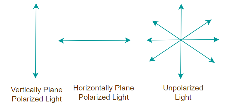
Polarized Light and Unpolarized Light
Polarized light and unpolarized light are two types of light that differ in the orientation of their electric field vibrations.
Polarized Light
Polarized light, on the other hand, refers to light in which the electric field vectors vibrate in a specific plane or direction. In polarized light, the electric field oscillations occur in a well-defined direction, rather than randomly. The process of transforming unpolarized light into polarized light is called polarization. Polarization can occur through various methods, such as reflection, transmission, scattering, or filtering.
Unpolarized Light
The light wave in which the electric field vectors vibrate in all possible directions perpendicular to the direction of propagation of the light is called unpolarized light. That is unpolarized light electric field vibrated randomly in all possible planes. We can define unpolarized light as a combination of light waves with all possible orientations of the electric field vectors. Sources of light such as the Sun or Incandescent bulbs emit unpolarized light.
Types of Polarization of Light
The three types of Polarization based on transverse and longitudinal wave motion are as follows:
- Linear polarization
- Elliptical Polarization
- Circular Polarization
Linear Polarization
In linear Polarization, the electric field of light is confined to a single plane along the direction of the propagation of light.
Elliptical Polarization
In Elliptical Polarization, the electric field of light propagates along an elliptical path. The two linear components do not have the same amplitude and phase difference in elliptical polarization.
Circular Polarization
In Circular Polarization, the electric field of light has two linear components that are perpendicular to each other and have identical amplitudes, but the phase difference is π ⁄ 2. The electric field that occurs will propagate in a circular motion.
Methods Used in Polarization of Light
There are a few different ways to polarize the light which are,
- Polarization by Transmission
- Polarization by Reflection
- Polarization by Scattering
- Polarization by Refraction
Polarization by Transmission (Polaroids)
We can observe that there is a plane of vibration parallel to the plane in the diagram below. There is also a vibration plane that is perpendicular to the plane. The first picture is one that is not polarised. The second picture is polarised, meaning it is perpendicular or parallel to the first. So let’s start with polaroids to understand polarization.
The various types of light are shown in the image added below:
Polaroids are polarising materials made up of molecules that are oriented in a specific direction. A pass axis exists on every Polaroid. Only the pass axis will enable light to flow through. Both the horizontal and vertical pass axes can exist on a polaroid. The way light passes through it is determined by these. When the light that is not polarised travels through a polaroid, it becomes polarised.
The unpolarized light passing through the polarizing filter is shown in the image below.
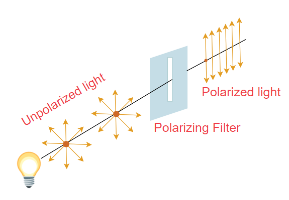
Polarization of Light
Polarization by Scattering
When light strikes a molecule or an atom, the light energy is absorbed and re-emitted in multiple directions. Polarization causes this scattering. Furthermore, the emitted light travels in many directions.
If the unpolarised light is incident on a particle, then we obtain dispersed light. Now when this polarized light passes through the atmosphere the molecule in the atmosphere dispersed the polarized light in all possible directions. And this is how light scattering causes polarization. The dispersed light is emitted in a direction that is perpendicular to the incident beam. Furthermore, dispersed light has complete polarization, but light travelling through molecules has partial polarization.
Polarization by Reflection and Refraction
The incident ray reflected and refracted ray may all be seen in the diagram below. Unpolarised light is visible on the incident beam. The unpolarized light is depicted in the diagram above. The dot denotes perpendicular directions, whereas the lines denote parallel directions.
The unpolarized light becomes polarized after reflection of refraction as shown in the image below.
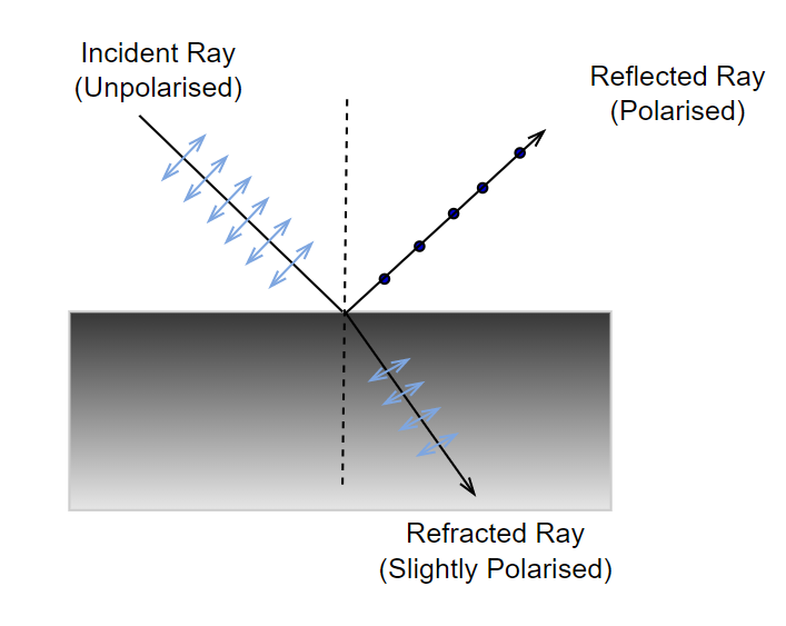
The majority of the light in the reflected ray is polarised parallel to the plane, with only a few exceptions. In contrast, most of the light in a refracted beam is unpolarized, with one or two polarised components. As a result, we can see that the reflected and refracted rays are both partly polarised.
How do Transverse Waves exhibit Polarization?
Any wave vibrating up and down perpendicular to the propagation of the wave is termed the transverse wave. As we know that a wave travels in 3-Dimensions and in the three dimensions there are two waves that are perpendicular to the propagation of the wave.
Suppose if we fix the propagation of the wave in the x-direction then it can oscillate in either the y-direction, z-direction or in a combination of both directions. Thus wave has two polarization in each y-direction and z-direction. This polarization of light can be measured using any polarized light-sensitive medium, such as lenses, prisms, and others.
Brewster’s Law
Brewster’s Law states that, for an unpolarized light of a known wavelength that is incident on a transparent surface, experiences maximum plan polarization at the angle of incidence then the tangent of the incidence angle is the refractive index of the substance for the given wavelength.
The law says that the reflected ray is fully polarised at a specific angle of incidence. The angle between the reflected and refracted rays is also 90°. Total Angle = 90° if i = iB, that is when the angle of incidence equals Brewster’s Angle.
According to Snell’s law,
μ = sin i ⁄ sin r
When light is incident at Brewster’s angle, then
iB + r = 90°
r = 90° − iB
Taking sin of the angles on both sides,
sin r = sin (90° − iB) = cos iB
Substituting this value of sin r in the formula of μ we get,
μ = sin iB ⁄ cos iB
μ = tan iB
Example: A beam of light strikes the surface of a plate of glass with a refractive index of √3 at the polarising angle. What will be the ray’s angle of refraction?
Solution:
Consider iP be the polarising angle,
Refractive Index,
μ = tan iP = √3
iP = 60°
Angle of refraction,
r = 90° – iP
⇒ r = 90° – 60°
⇒ r = 30°
Hence, the angle of refraction is 30°.
Applications of Polarization of Light
Polarization is a very important phenomenon of physics and some of its common applications are,
- Polarization is used to determine the chirality of organic molecules.
- Differentiating between transverse and longitudinal waves is done via polarization.
- In the plastics industry, Polaroid filters are used to conduct stress analysis testing.
- Polarization is used to create and display three-dimensional movies.
- In sunglasses, polarization is used to minimize glare.
- It’s used to analyze earthquakes in seismology.
- Polarization is used in infrared spectroscopy.
Important Physics Related Links:
- Photon Definition
- What Is Escape Velocity
- Properties Of Metamorphic Rocks
- Fission Vs Fusion
- What Is Electrostatic
- The Density Of Water Is Maximum At
- Si Unit For Volume
- All Electrical Symbols
- Newton’s Second Law Statement
- What Is Brownian Motion
Summary – Polarization of Light
Polarization of light is like giving direction to the chaotic dance of light waves. Imagine light as a crowd of people moving together but facing all different directions; polarization is like getting them all to move in harmony, facing the same way. It’s a process that turns the jumbled mess of directions in unpolarized light into a neat, single direction in polarized light.
This happens naturally, like when sunlight bounces off a lake, or artificially with special materials called polaroids that act like gatekeepers, only letting light waves through if they’re moving in the right direction.
This isn’t just for show; it has practical uses, like reducing glare in sunglasses, analyzing chemicals, and even making 3D movies pop. It’s a fascinating aspect of light that shows just how complex and useful this everyday phenomenon can be.
Polarization – FAQs
What is Polarization?
The process of converting ordinary light to plane-polarized light is called Polarization.
Which phenomenon causes polarization of light?
Polarization of light is caused by Double Refraction of the light.
How many types of polarization?
There are basically three types of Polarization,
- Linear Polarization
- Circular Polarization
- Elliptical Polarization
How does polarized light differ from ordinary light?
The basic difference between polarized light and ordinary light is,
“Polarized Light Oscillates at a single phase in a particular plane whereas ordinary light has no plane and it vibrates at random angles.”
How polarized light is produced?
Polarized Light is produced by various methods which include,
- Polarization by Reflection
- Polarization by Refraction
- Polarization by Scattering
- Polarization by Transmission
Who discovered the polarization of light?
The phenomenon of polarization of light is discovered by famous French physicist Etienne Louis Malus.
0 Comments