
CBSE Class 12 Physics Notes Chapter 3 – Current Electricity
Current Electricity is the third chapter of Class 12 Physics, which is an extension of the previous year’s classes on the same topic. Here, all the previously studied topics are again introduced but with very detailed explanations which help clear out the doubts of the previous year’s class where understanding of the current and electricity is very simple. In his chapter, we study not only the foundational topics but the further extension of electricity and various equipment related to it and study all the following topics:
- Electric Current
- Electric Currents in Conductors
- Ohm’s Law
- Drift of Electrons
- Origin of Resistivity
- Limitations of Ohm’s Law
- Temperature Dependence of Resistivity
- Electrical Energy, Power
- Combination of Resistors — Series and Parallel
- Cells, Emf, Internal Resistance
- Cells in Series and in Parallel
- Kirchhoff’s Rules
- Wheatstone Bridge
- Meter Bridge
- Potentiometer
Electric Current
Electric current is the type of energy that is responsible for the working of modern-day society. We define electric current as the flow of electric charge. Electric current is used to power our everyday life, we use mobiles, computers, ACs, TVs, Fridges, etc in our daily life all these are powered by electric current. Electric current is the flow of the electron in the circuit that allow the electric energy to flow which changes into a different form of energy accordingly.
In this article, we will learn about Electric Current, its unit, properties of electric current, Ohm’s law, the effect of electric current, etc, and others in detail.
Table of Content
What is Electric Current?
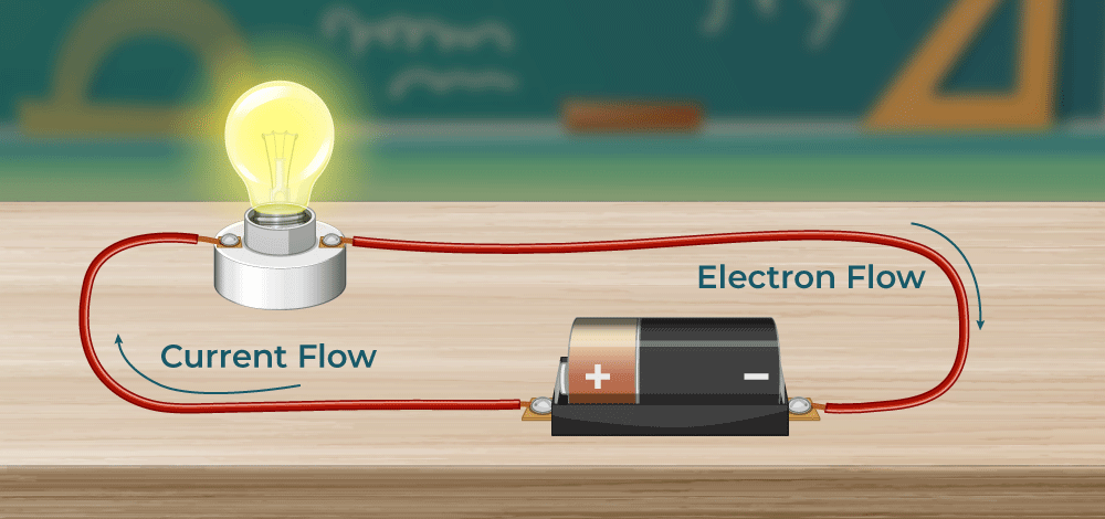
The flow of electric charges is known as electric current. In earlier times, it was considered that correct flow was due to the movement of positive charges from the positive terminal to the negative terminal. But after the discovery of electrons, the conventional wisdom was proven wrong as the positive charge is nothing but the deficiency of the electron.
Now, scientists know that current itself is generated due to the movement of negative charges (electrons), electron flow from the negative terminal of the system to the positive terminal, which is known as Electron flow, and unlike electrons, current flows in the opposite direction i.e., from the positive terminal to negative terminal, which is also known as Conventional Current flow.
Electric Current Definition
Electric current is the flow of electric charge through a conductor. It is a measure of the rate at which electric charge passes through a particular point in a circuit. In simpler terms, electric current is the movement of electrons or ions in a closed circuit, typically resulting from the presence of a voltage difference across the circuit.
The best way to imagine current flowing in a circuit is by imagining the flow of liquid inside a pipe from a higher point to a lower one, the liquid represents current, and the difference in the heights of the extreme end of the pipe represents the difference in potential causing the current to flow if the pipe is twisted at some point the flow of the liquid will slow down, that represents the resistance offered by the conductor that reduces the current.
Materials that easily let electrons move from one place to another are called conductors. These materials make it easy for electric charge to pass through them because electrons can move around freely. When electrons move through a conductor, it creates electric current. The force needed to make the current flow through a conductor is called voltage.
Examples of conductors are the human body, salty water, and metals like iron, silver, and gold.
On the other hand, insulators are materials that don’t let electrons move around freely. This means electric charge can’t flow easily through them. Because of this, the charge usually stays put and doesn’t spread out evenly over an insulator‘s surface.
Examples of Insulators include plastic, wood, and glass.
Check: Electric Current in Conductors
Electric Current Formula
The electric current can be represented as the rate of flow of electric charge (q) which mathematically can be represented as follows:

Unit of Electric Current
As Electric Charge and Time come under the Fundamental quantities and their units are respectively Coulomb and second. So by the definition of Electric Current, its unit is Coulomb/second.
- In the SI Unit of Electric Current is Ampere (A).
- In the CGS system, the unit of Electric Current is Biot or sometimes called an Abaampere.
Fact: Silver is the best at conducting electricity.
Check: Electric Current Formula
What Is Electromotive Force or EMF?
Normally, in a conductor, Electrons are present, and they are not stationary, they keep on moving in random directions, and due to their randomness, the overall displacement of all electrons becomes zero, and hence, no current is produced. In order to produce current, some external force is required to align electrons in one direction and make them move in that one direction, this external force is known as Electromotive Force and is also famous as EMF. It is nothing but the voltage applied to produce current.
Types of Electric Current
There are two types of electric current, that are,
- Alternating Current
- Direct Current
Alternating Current
Electric current with its direction and values keep changing is known as Alternating Current. The values of AC in one direction increase from 0 to peak value then falls down to 0 again, then in opposite direction increase from 0 to peak value then come back to 0.
As electric current goes from 0 to peak in one direction and the same in the opposite direction, it behaves like a wave more specifically a sine wave and it has some frequency. For example, in India, the grid provides 60 Hertz 220 Volts AC but in America, their grid provides 120 Volts 50 hearts AC.
Direct Current
Electric current with the same direction always is known as Direct Current. As the direction of DC remains the same, so its frequency is 0.
Check Types of Current
Conventional Current Flow Vs Electron Flow
| Aspect | Conventional Current Flow | Electron Flow |
|---|---|---|
| Description | Traditional description of electric charge movement | Modern and accurate description of electric charge movement |
| Direction of Current | Positive terminal to negative terminal of voltage source | Negative terminal to positive terminal of voltage source |
| Basis | Established before the discovery of the electron | Based on the movement of electrons through conductors |
| Charge Movement | Positive charges are considered to move in the direction of current | Negatively charged electrons move in the direction of current |
| Accuracy | Historically used but not reflective of actual charge movement | Reflects the actual movement of charge in a circuit |
Properties of Electric Current
Various properties of Electric Current are :
- Current is due to the Flow of electrons in the circuit.
- Electric current can be categorized as AC and DC in nature, where DC is the direct current that flows in only one direction, DC is used in low-voltage applications, aircraft applications, etc. AC is known as alternating current, and it flows in both directions alternatively, AC is the current that comes in our houses, and the appliances work on AC.
- The electric current in a circuit can be controlled by introducing resistance to the circuit.
- The unit of Electric current is Amperes (A). 1 Ampere can be defined as the flow of 1 coulomb of charge in 1 second.
- Electric current flows from Higher potential to Lower Potential in a circuit (from positive terminal to negative terminal) also known as the conventional current flow direction.
Ohm’s Law
German physicist Georg Simon Ohm stated that the current flowing in a wire is directly proportional to the voltage drop across it. According to Ohm’s Law, the current flowing through a wire is directly proportional to the voltage applied at the ends of the wire provided that the temperature and conductivity remain the same.
V ∝ I
Upon removing the proportionality sign, a proportionality constant is introduced known as Resistance.

Where,
- V is Voltage at the ends of conductor
- R is Resistance offered by the conductor
- I is Current through the wire
Ohm’s law can be illustrated using the following illustration,

Effects of Electric Current
There are different effects that can be noticed due to the flow of electric current in a wire, for example, when current passes through a resistor, the resistor has a property of resisting which does not let the whole current pass but since energy can neither be created nor destroyed, it is converted in heat energy and is released in the form of heat, this effect is called as the heating effect of current. Similarly, we have the magnetic and chemical effects of electric current.
1. Chemical Effect of Electric Current
When Electric current is passed through a which is conducting in nature, the solution breaks in its respective ions, and effects are seen visibly. The major effects that are prominent,
- The color of the solution may change.
- The deposition of metal at the electrodes may be seen.
- There can be the formation of gas bubbles at the electrodes.
2. Magnetic Effect of Electric Current
Electric current is nothing but the motion of electrons, and it is known, when charges are stationary, they create Electric Field but when charges are in motion, they create a Magnetic field. When current is passed through a wire and a metallic sheet is placed there with a needle, the needle will be deflected due to the presence of a magnetic field which is produced by the electric current. One of the biggest applications of the Magnetic effect of electric current is Electromagnets, they are formed with the help of passing current.
3. Heating Effect of Electric Current
When current flows in a conductor, heat energy is produced and released from the conductor and the amount of effect depends upon the resistance offered by the conductor. If the conductor has to offer high resistance, it simply means that it shall not allow most of the current to flow but due to the conservation of energy (energy can neither be created nor destroyed), current that could not pass is converted into heat and the phenomenon is known as the Heating effect of current. The formula for heat energy is given by,

Where,
- H is Heat energy released
- I is current flowing in the conductor
- R is Resistance offered by the conductor
- T is Time for which the current was flowing in the conductor
Applications of the heating effect of current involve Electric Irons, Electric Heaters, filament lamps, Electric kettles, etc.
Read More,
Solved Examples of Electric Current
There are some solved examples of electric current for better understanding given below :
Example 1: In a conductor, 10 Coulombs of charge flow for 5 seconds, determine the current produced.
Solution
The current in a circuit is given by,
I = q/t
⇒ I = 10/5 Amperes
⇒ I = 2 Amperes
Therefore, 2 amperes of current flows in the circuit.
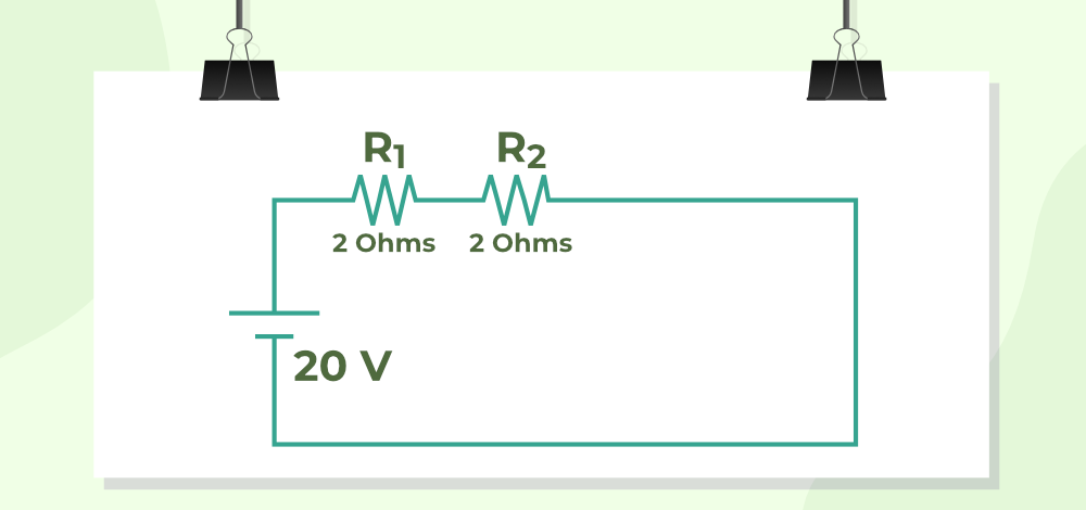
Example 2: In the circuit given below, Find the current flowing through the circuit.
Solution
In the figure provided, it is clear that there are two resistances, and they are in series.
R = R1 + R2
⇒ R = 2+ 2
⇒ R = 4 ohms
From Ohms Law,
V = IR
⇒ I = V/R
⇒ I = 20/4
⇒ I = 5 Amperes
Example 3: What is the Heat energy produced when 2 amperes of current is flowing in a circuit for 5 seconds having an overall resistance in the circuit of 4 ohms?
Solution
Heat Energy Produced is given by,
H = I2RT
⇒ H = (2)2×4 × 5
⇒ H = 16 × 5
⇒ H = 80 Joules
Therefore, 80 Joules heat is produced in the circuit.
Electric Current – FAQs
What is electric current?
Electric current is the flow of electric charge through a conductor, typically measured in amperes. It occurs when there is a voltage difference across a conductor.
What is SI Unit of Electric Current?
SI Unit of Electric Current is Ampere.
Define Ampere.
In a conductor if 1 Coulomb of charge passes in 1 second of time, then we say 1 Ampere current is flowing through that conductor.
How does electric current work?
Electric current flows when electrons move through a conductor, such as a wire, driven by a voltage difference applied across it. This movement is typically from a negative to a positive terminal.
What are the types of electric current?
There are two main types: direct current (DC), where the flow of electricity is in one direction, and alternating current (AC), where the current reverses direction periodically.
What are the effects of electric current?
Electric current can produce several effects, notable among them are heating effect, magnetic effect, and chemical effect, each playing a crucial role in various applications like heating, motors, and batteries.
How is electric current used in everyday life?
Electric current is essential in powering household appliances, lighting, heating systems, and in larger scales, it drives machinery and public transport systems.
What are common safety tips for handling electric current?
Safety tips include avoiding water when handling electrical devices, using insulated tools, not overloading circuits, and ensuring all electrical installations comply with local safety standards.
An Instrument Detects Electric Current is known as________.
Instrument for measuring electric current is known as Ammeter.
Electric Current in Conductors
Electric current in conductors is the movement of electric charge through a substance, usually a metallic wire or other conductor. Electric current is the rate at which an electric charge flows past a certain point in a conductor, and it is measured in amperes.
When a potential difference (voltage) is supplied across the ends of a conductor, it induces an electric field within the material. This electric field exerts force on the free electrons in the conductor, causing them to migrate. In this article, we will learn in detail about the electric current in conductors.
What is Electric Current?
Electric current is defined as the rate at which electric charge flows past a given point in a circuit. It’s measured in amperes (A), where 1 ampere is equivalent to 1 coulomb of charge flowing per second.
Ohm’s Law
Ohm’s Law describes the relationship between current, voltage, and resistance in a circuit. It states that the current (I) flowing through a conductor is directly proportional to the voltage (V) applied across it and inversely proportional to the resistance (R) of the conductor, expressed by the equation
I = V/R
In a given time interval “t”, the charge passing through the surface can be divided into two parts – positive charges and negative charges. Let’s say q+ is the net positive charge passing through the surface in the given time interval, similarly q– is the net negative charge passing through the surface in the given time interval. In this case, the net charge passing through this surface in this interval will be,
qnet = q+ – q–
Electric current in defined as the rate of flow of charge in a conductor.
Here, I represents the average current flowing through the surface.
The unit for current is Ampere (A), Ampere stands for Column/sec.
In case when the rate of flow of charge is varying, the current flowing is given by,
I = dQ/dt
Where:
- I represents the current (measured in amperes, A)
- dQ/dt represents the rate of change of charge with respect to time (measured in coulombs per second, C/s or A)
What is Conductors?
Conductors are materials that allow electric current to flow through them easily. In these materials, electric charge carriers, typically electrons, are free to move. Metals like copper, silver, gold, and aluminum are excellent conductors of electricity due to their atomic structure.
In conductors, electrons are loosely bound to their atoms, allowing them to move relatively freely in response to an electric field. When a voltage is applied across a conductor, an electric current is established as electrons drift from areas of higher potential (positive) to areas of lower potential (negative).
Types of Conductors
These are some of the main types of conductors, each with its own unique properties and applications.
- Metallic Conductors: These are the most common type of conductors and include metals like copper, aluminum, silver, and gold.
- Superconductors: Superconductors are materials that can conduct electricity with zero resistance when cooled below a critical temperature.
- Semiconductors: While semiconductors like silicon and germanium are not as good conductors as metals, they can still carry electric current.
Electric Currents in Conductors
An electric charge experiences force if an electric field is applied, due to the force it starts moving and the movement of these charges constitutes the electric current. In a solid conductor, atoms are tightly bound with each other and approximately all the electrons are bound to the atoms. There are some electrons that are free from all the atoms are able to move freely throughout the material. When no electric field is applied, these electrons perform motion in random directions. At a given time, there is no preferential direction for the velocities of the electrons. This means, on average the number of electrons travelling in any direction will be equal to the number of electrons travelling in the opposite direction. So, there will be no net electric current.
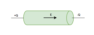
Let’s see how these electrons behave when an electric field is applied to the conductor. Imagine a conductor given in the figure above, suppose one is a positively charges cylindrical disc and a negatively charged cylindrical disc. These discs are kept at the ends of a cylindrical conductor. An electric field will be created inside the conductor, this field will exert the force of charges and they will move. The movement of charges causes the electric current
Direction of Electric Current in Conductor
The direction of electric current in a conductor is defined as the direction in which positive charge carriers would flow if they were free to move. However, in most metallic conductors, such as wires, the charge carriers are negatively charged electrons, which actually move in the opposite direction of conventional current flow.
Related Articles
Sample Problems on Electric Current in Conductors
Question 1: Assume a horizontal plate and positive charge of 50C flows in 5 seconds through that plate. Find the magnitude of the electric current passing through that plate.
Answer:
It is known that electric current is the rate of charge passing through the conductor.
Net charge passing through the conductor qnet = 50C
Time taken, t = 5
⇒
⇒ I = 10 A


Question 2: Assume a horizontal plate and positive charge of 20C flows in 2.5 seconds through that plate. Find the magnitude of the electric current passing through that plate.
Answer:
It is known that electric current is the rate of charge passing through the conductor.
Net charge passing through the conductor qnet = 20C
Time taken, t = 2.5
⇒
⇒ I = 8 A

Question 3: The charge present inside the conductor at a given time is given by the function q(t) below.
q(t) = sin(t)
Find the current flowing through the conductor at time t.
Answer:
In this case, the rate of charge through the conductor is changing. So, average current cannot be calculated, for such case instantaneous current is calculated.
⇒
⇒ I = cos(t) A


Question 4: The charge present inside the conductor at a given time is given by the function q(t) below.
q(t) = t2 + 2t
Find the current flowing through the conductor at time t = 2.
Answer:
In this case, the rate of charge through the conductor is changing. So, average current cannot be calculated, for such case instantaneous current is calculated.
⇒
⇒
⇒ I = 2t + 2
at t = 2.
I = 2(2) + 2
⇒ I = 4 + 2
⇒ I = 6 A


Question 5: The charge present inside the conductor at a given time is given by the function q(t) below.
q(t) = t + 2t3 + et
Find the current flowing through the conductor at time t = 1.
Answer:
In this case, the rate of charge through the conductor is changing. So, average current cannot be calculated, for such case instantaneous current is calculated.
⇒
⇒ )
⇒ I = 1 + 6t2 + et
at t = 1.
I = 1 + 6t2 + et
⇒ I = 1 + 6(1) + e
⇒ I = 7 + e
⇒ I = 9.7A


FAQs on Electric Current in Conductors
What factors affect the flow of current in a conductor?
The flow of current in a conductor depends on its resistance, voltage applied, and the material of the conductor. Higher resistance reduces current flow, while higher voltage increases it.
What is resistivity?
Resistivity is a property of materials that determines how strongly they oppose the flow of electric current. It’s measured in ohm-meters (Ω⋅m).
What is meant by the term ‘electric circuit’?
An electric circuit is a closed loop through which electric current can flow. It typically consists of a power source (such as a battery or generator), conductors, and loads (such as resistors or appliances).
What is electric current?
The current of electricity is the process of an electric charge flow through a conductor and is measured in amperes (A).
Is it possible that the electric current flowing in a vacuum?
Not really! Electric current involves the motion of charged particles along with conductors or electrolytes.
What is the reason that conductors get hot when current passes on them?
Resistance to the electronic current flow produces heat energy according to Joule’s Law.
Ohm’s Law – Definition, Formula, Applications, Limitations
According to Ohm’s law, the voltage or potential difference between two locations is proportional to the current of electricity flowing through the resistance, and the resistance of the circuit is proportional to the current or electricity travelling through the resistance. V=IR is the formula for Ohm’s law. Georg Simon Ohm, a German physicist, discovered the connection between current, voltage, and relationship. Let’s take a closer look at Ohms Law, Resistance, and its applications.
What is Ohm’s Law?
Voltage, current, and resistance are the three most fundamental components of electricity. Ohm’s law depicts a straightforward relationship between these three variables. According to Ohm’s law, the current flowing through a conductor between two locations is proportional to the voltage across the conductor.
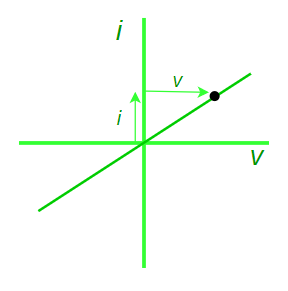
Voltage-Current Relationship Diagram
Ohm’s Law Formula
This is one of the most fundamental electrical rules. It aids in the calculation of an element’s power, efficiency, current, voltage, and resistance in an electrical circuit.
V ∝ R
V = I × R
Here,
- V is the voltage,
- I is the current, and
- R is the resistance.
The SI unit of resistance is ohms and is denoted by Ω.
Applications of Ohm’s Law
When the other two numbers are known, Ohm’s law may be used to determine the voltage, current, impedance, or resistance of a linear electric circuit.
Main applications of Ohm’s Law:
- It also simplifies power calculations.
- To keep the desired voltage drop between the electrical components, Ohm’s law is employed.
- An electric circuit’s voltage, resistance, or current must be determined.
- Ohm’s law is also utilised to redirect current in DC ammeters and other DC shunts.
How do we establish a current-voltage relationship?
The ratio V ⁄ I remains constant for a given resistance while establishing the current-voltage connection, hence a graph of the potential difference (V) and current (I) must be a straight line.
How can we discover the unknown resistance values?
The constant ratio is what determines the unknown resistance values. The resistance of a wire with a uniform cross-section relies on the length (L) and the cross-section area (A). It also relies on the conductor’s temperature.
The resistance, at a given temperature,
R = ρ L ⁄ A
Here, ρ is the specific resistance or resistivity and is the wire material’s characteristic.
The wire material’s specific resistance or resistivity is,
ρ = R A ⁄ L
Limitations of ohms law
- The law of Ohm does not apply to unilateral networks. The current can only flow in one direction in unilateral networks. Diodes, transistors, and other electronic components are used in these sorts of networks.
- Non-linear components are also exempt from Ohm’s law. Non-linear components have a current that is not proportional to the applied voltage, which implies that the resistance value of those elements varies depending on the voltage and current. The thyristor is an example of a non-linear element.
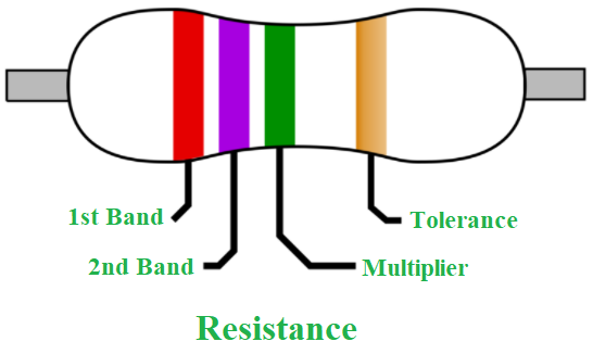
Resistors
One of the most important components in electrical circuits is the resistor. Because they are comprised of a clay or carbon combination, they are good conductors and good insulators. Four colour bands are seen on the majority of resistors. The first and second bands show the value’s first and second digits, respectively. The value digits are multiplied in the third band, and the tolerance is determined in the fourth band. If there isn’t a fourth band, the tolerance is presumed to be plus or minus 20 %.
Resistance in series
A series is a group of related items, such as along a line, in a row, or in a certain order. In electronics, series resistance implies that the resistors are linked in series and that current can only travel via one channel.
Laws of Series Circuits
- The overall circuit resistance is made up of individual resistances.
- The total voltage is the sum of the individual voltages in the circuit.
- Every point in the circuit has the same amount of current flowing through it.
Resistance in parallel
A parallel circuit can be organised in a variety of ways. The majority of wiring in the real world is done in parallel, such that the voltage provided to any one portion of the network is the same as the voltage given to any other section of it.
Laws of Parallel Circuits
- All of the component resistances’ reciprocals add up to the overall circuit resistance’s reciprocal.
- The total current draw is the sum of individual current pulls across the circuit.
- Every point in the circuit has the same voltage.
Sample Problems
Problem 1: Find the resistance of an electrical circuit with a voltage supply of 15 V and a current of 3 mA.
Solution:
Given:
V = 15 V,
I = 3 mA = 0.003 A
The resistance of an electrical circuit is given as:
R = V / I
= 15 V / 0.003 A
= 5000 Ω
= 5 kΩ
Hence, the resistance of an electrical circuit is 5 kΩ.
Problem 2: If the resistance of an electric iron is 10 Ω and a current of 6 A flows through the resistance. Find the voltage between two points.
Solution:
Given:
I = 6 A
R = 10 Ω
The formula to calculate the voltage is given as:
V = I × R
V = 6 A × 10 Ω
= 60 V
Hence, the voltage between two points is 60 V.
Problem 3: When does Ohm’s law fail?
Solution:
The behaviour of semiconductors and unilateral devices like diodes defines Ohm’s law. If physical factors such as temperature and pressure are not kept constant, Ohm’s law may not provide the intended effects.
Problem 4: Why doesn’t Ohm’s law apply to semiconductors?
Solution:
Semiconducting devices are nonlinear in nature due to which Ohm’s law does not apply to them. This indicates that the voltage-to-current ratio does not remain constant when voltage varies.
Problem 5: What is the application of Ohm’s Law?
Solution:
The static values of circuit components such as current levels, voltage supplies, and voltage drops are validated using Ohm’s law.
Resistivity
Resistance is the physical property of the material which opposes the current flow in the circuit whereas resistivity is the intrinsic property that helps us understand the relation between the dimension of the substance and the resistance offered by it.
In this article, we will learn about Resistance, Resistivity, how resistance and resistivity are related to each other, the difference between resistance and resistivity, and others in detail.
Resistance Definition
Let’s consider water flowing through a pipe encounters resistance to its flow like bending or squeezing of pipe, then the flow of water is decreased significantly. Similarly, if the current is considered as water and the pipe is considered to be the conductor through which the current is flowing, then bending and squeezing or any other form of disturbance can be visualized as resistance.
Resistance is the property of substance due to which is opposes the current flowing through the conductor, and according to ohm’s law for resistance,
R = V/I
Where,
- R is Resistance of the conductor
- V is Voltage across the conductor
- I is Current across the conductor.
Unit of Resistance
SI unit of the resistance is “ohms” which is denoted by Ω
Resistivity Definition
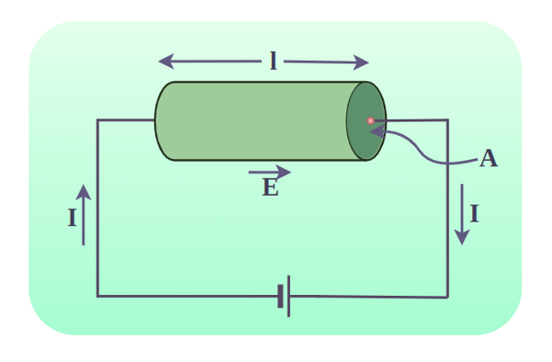
When a voltage is applied to a conductor, the electric field E is created inside it which pushes the charges to move. The current density that gets developed depends on the material and the electric field that is created. This density can be very complex but under reasonable assumptions, including assuming the metals are at room temperature. This relation can be modeled using,
J = σE
Here, σ is the electrical conductivity.
Electrical conductivity is the measure of the material to conduct electricity. Conductors have more electrical conductivity than insulators. Conductivity is an intrinsic property of material, another intrinsic property of the material is the resistivity of electrical resistivity. It is a measure of how strongly a material opposes the flow of charges. It is denoted by the lowercase Greek letter rho(ρ). The electrical resistivity is reciprocal of the electrical conductivity.
ρ = 1/σ
Electrical Resistivity measures the intrinsic resistance of the material and is the fundamental property of the material. Other than depending on the electrical conductivity, resistivity also depends upon the temperature, type of material, impurities in the material, and the physical structure of the material as well. Generally, metals have low resistivity, which means they are good conductors and non-metals have high resistivity, which means they are bas conductors.
Resistivity Formula
The formula to calculate the resistivity of any material is,
ρ = RA/l
where,
- ρ is the resistivity of the material and is measured in Ω.m
- R is the electrical resistance of uniform cross-sectional material and is measured in Ω
- l is the length of a piece of material and is measured in m
- A is the cross-sectional area of the material and is measured in m2
We can also measure the resistivity of the material if the Electric Field and Current Density are given as,
ρ = E/J
where,
- ρ is the resistivity of the material and is measured in Ω.m
- E is the magnitude of the electric field and is measured in V.m-1
- J is the magnitude of current density and is measured in A.m-2
Learn more about, Resistance Formula
Unit of Resistivity
- The SI unit of resistivity is ohm-meter which is denoted by Ω-m.
- In the CGS system, the unit of Resistivity is Ω-cm.
- The dimension of resistivity is M1L3T-3A-2
Resistivity of Different Materials
The table for resistivity and conductivity for various materials is given as follows:
Material | Resistivity, ρ (Ω⋅m) | Conductivity, σ (Ω⋅m)−1 |
|---|---|---|
Conductors | ||
| Silver | 1.59×10⁻⁸ | 6.29×10⁷ |
| Copper | 1.68×10⁻⁸ | 5.95×10⁷ |
| Gold | 2.44×10⁻⁸ | 4.10×10⁷ |
| Aluminum | 2.65×10⁻⁸ | 3.77×10⁷ |
| Iron | 9.71×10⁻⁸ | 1.03×10⁷ |
| Lead | 22.00×10⁻⁸ | 0.45×10⁷ |
| Mercury | 98.00×10⁻⁸ | 0.10×10⁷ |
| Nichrome (Ni, Fe, Cr alloy) | 100.00×10⁻⁸ | 0.10×10⁷ |
| Platinum | 10.60×10⁻⁸ | 0.94×10⁷ |
| Tungsten | 5.60×10⁻⁸ | 1.79×10⁷ |
Semiconductors | ||
| Carbon (Pure) | 3.50×10⁻⁵ | 2.86×10⁴ |
| Carbon | (3.5−60)×10−5 | (2.86−1.67)×10-6 |
| Silicon (Pure) | 2300 | – |
| Silicon | 0.1 – 2300 | – |
Insulators | ||
| Glass | 109−1014 | 10−9−19−14 |
| Mica | 1011−1015 | 10−11−10−15 |
| Quartz (Fused) | 75×1016 | 1.33×10⁻¹⁸ |
| Rubber (Hard) | 1013−1016 | 10−13−10−16 |
| Wood | 108−1011 | 10−8−10−11 |
Relation of Resistance and Resistivity
As our previous analogy of resistance, where resistance is analogous to the water. The resistance in the flow of water is directly proportional to the length (the longer the pipe harder to pump water through it)of the pipe and inversely proportional to the cross-sectional area of the pipe (the wider the pipe, the more water can flow through it), similarly, resistance offered by a conductor is directly proportional to the length of conductor and inversely proportional to the cross-sectional area of the conductor.
Thus, the resistance of the conductor is given by,
R ∝ l/A
R = ρl/A
where, R is Resistance
l is length of wire
A is cross sectional area of wire
ρ is Resistivity
Specific Resistivity
The resistivity of material for the unit length and unit cross-sectional area is called Specific Resistivity and it means how strongly a material with unit length and unit cross-sectional area, can resist the flow of current.
In other words, specific resistivity the resistance of the material, if it’s the length and cross-sectional area, becomes unity.
R = (ρ×1)/1
R = ρ
Difference Between Resistance and Resistivity
There are various differences between Resistance and Resistivity, some of those differences are as follows:
Resistance | Resistivity |
|---|---|
| Resistance of the substance is its physical property of resisting the flow of current i.e. electrons. | Resistivity of the substance is its intrinsic property and is the measure of how strongly the substance can resist the flow of current. |
Resistance is directly proportional to the length and temperature while it is inversely proportional to the cross-sectional area of the material i.e., ρ = (R×A)/l Where R is resistance, l is the length of the conductor, and A is the cross-sectional area of the conductor. | Resistivity only depends on the temperature, type of material, impurities, physical structure, and conductivity of the material. As ρ = 1/σ Where σ is the conductivity of the material. |
| In electrical circuits, resistance is represented by R. | In electrical circuits, resistivity is denoted by ρ |
The formula for calculating the resistance of a circuit is given by Ohm’s law i.e., R = V/I Where V is voltage and I is current passing through the material. | The formula for calculating the resistivity is given by J = σE or Where J is the current density, E is the electric field intensity, and σ is the conductivity of the material. |
| SI unit of resistance is the ohm(Ω). | SI unit of Resistivity is ohm-meter (Ω-m). |

Resistor Colour Coding
Resistors are used to control the flow of the current in the electric circuit. The resistance in the resistor is shown using different color codes. Different color codes in the resistor specify different values of the resistance.
A resistor has four different color codes that specify the value of resistance of the resistor. The color in the resistor band specifies different values of the resistance, such as black color specifies the 0 value, and brown color specifies the 10 value with ±1% tolerance.
Read More,
Sample Problems on Resistance and Resistivity
Problem 1: A battery of 5 Volts connected to a conductor induces a current of 10mA in the conductor. Find the resistance of the conductor.
Answer:
Resistance of conductor is given by the relation,
R = V/I
Given:
- V = 5 V
- I = 10 mA = 0.01 A
Plugging in the values inside the relation,
R = V/I
⇒ R = (5)/(0.01)
⇒ R= 500 Ω
Problem 2: A battery of 20 Volts connected to a conductor induces a current of 50mA in the conductor. Find the resistance of the conductor.
Answer:
Resistance of conductor is given by the relation,
R = V/I
Given:
- V = 20 V
- I = 50 mA = 0.05 A
Plugging in the values inside the relation,
R = V/I
⇒ R = (20)/(0.05)
⇒ R= 400 Ω
Problem 3: A battery of 100 Volts connected to a material induces a current of 0 mA in the conductor. Find the resistance of the material.
Answer:
Resistance of conductor is given by the relation,
R = V/I
Given:
- V = 20 V
- I = 0 mA = 0 A
Plugging in the values inside the relation,
⇒ R = (20)/(0) = Not defined
Resistance approaches to infinity, which means the material is an insulator.
Problem 4: A cylindrical conductor of length 0.5m and cross-sectional area 0.01 m2. The resistivity of the material is 2 x 10⁻⁸ ohm-m. Find the resistance of the material.
Answer:
Resistance of a conductor is given by,
ρ = (R×A)/l
Given:
- l = 0.5m
- A = 0.01 m2
- ρ = 2 x 10⁻⁸
Plugging the values in the relation given above,
⇒ R =
⇒ R = 10-6 Ω

Problem 5: A cylindrical conductor of length 2m and cross-sectional area 0.05 m2. The resistivity of the material is 4 x 10⁻⁸ ohm-m. Find the resistance of the material.
Answer:
Resistance of a conductor is given by,
ρ = (R×A)/l
Given:
- l = 2m
- A = 0.05 m2
- ρ = 4 × 10⁻⁸
Plugging the values in the relation given above,
⇒ R =
⇒ R = 1.6 × 10⁻⁶ Ω

FAQs on Resistance and Resistivity
Q1: What is Resistance?
Answer:
Resistance is the physical property of the material to resist the flow of electricity passing through it when an external voltage is applied.
Q2: What is Resistivity?
Answer:
Electrical resistivity of the intrinsic property of the material and is a measure of how strongly the material can resist the flow of current through it.
Q3: How are Resistance and Resistivity related?
Answer:
Resistance and resistivity are related by the formula which is given by:
R = ρl/A
Where,
- R is the resistance of the conductor,
- l is the length of the conductor,
- A is the cross-sectional area of the conductor, and
- ρ is the proportionality constant which represents resistivity.
Q4: What is the Difference between Resistance and Resistivity?
Answer:
The key difference between resistance and resistivity is that resistance is the physical property of the material i.e., it depends on the physical things like dimensions of the material. On the other side resistivity is the intrinsic property i.e., it is the inherent property of the substance and doesn’t depend on physical factors.
Q5: What is SI unit of Electrical Resistivity?
Answer:
The SI unit of Electrical Resistivity is Ω-m.
Temperature Dependence of Resistance
Devices such as batteries, cells, etc. are essential for maintaining a potential difference across the circuit and are referred to as voltage sources. When a voltage source is connected across a conductor, it creates an electric field which causes the charges to move and this causes current. The values of the current that are generated strictly depends on the characteristic of the material. Any material opposes the flow of electric charge which is called resistance. It is developed due to resistivity which is a property of the material. Let’s see how these properties change with temperature when it is varied.
Resistance
Water flowing through a pipe encounters resistance to its flow if the current is considered as water and the pipe is considered to be the conductor through which the current is flowing. The same analogy can be used to deduce the obstruction of flow in the case of current too. This obstruction of flow against the current is termed Resistance. The resistance in a wire experiencing a current I and voltage V is defined as,
R = V/I
Here, R denotes the resistance of the wire. Its unit is “ohms” which is denoted by Ω
Notice in the relation, the resistance depends inversely on the current flowing through the wire. Thus, the more the resistance of the wire, the less is the current flowing through it, which can also be deduced from the intuitive definition of the resistance.
Resistance of a Wire
Picking the previous example of flowing water, one can draw the similarities between these two very different physical processes. The resistance offered to the water flowing through the pipe majorly depends on the length of the pipe and its cross-sections. In a similar way, the resistance offered by a conductor depends on the conductor’s size, shape, and material. The figure below shows a conductor which the length l, cross-sectional area A and resistivity (rho).
The resistance of the conductor is given by,
R = ρl/A
Notice that, the resistance is proportional to the length of the conductor but inversely proportional to the cross-sectional area of the conductor.
Resistivity
When a voltage is applied to a conductor, the electric field E is created inside it which pushes the charges to move. The current density that gets developed depends on the material and the electric field that is created. This density can be very complex but under reasonable assumptions, including assuming the metals at room temperature. This relation can be modeled using,
J = σE
Here, σ is the electrical conductivity.
The unit of resistivity is given by ohm-meter(Ω-m).
Temperature Dependence of Resistivity
As mentioned in the formula above, the resistance of a material. depends on its resistivity, shape, and size. Resistance of a material depends on how the shape changes with temperature and resistivity variations with temperature. Resistivity behaves differently with temperature for different materials. Typically, conductors have low resistivity while insulators have high resistivity. Resistivity varies in a different manner for different materials. In general, for metallic conductors,
The resistivity of metallic conductors within a limited range of temperature is given by the following equation:
ρT = ρ0[1 + a(T – T0)]
Here,
ρT = Resistivity at temperature T,
ρ0 = Resistivity at temperature T0,
a = temperature coefficient of resistivity.
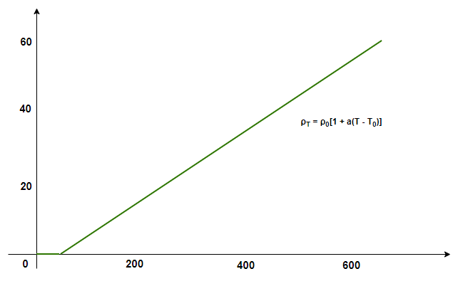
Resistivity varies differently with different materials. For example, materials like Manganin, Nichrome are less likely to change their resistivity with temperature. In the case of semiconductors, their resistivity decreases with temperature.
Sample Problems
Question 1: A battery of 20 Volts connected to a conductor induces a current of 20mA in the conductor. Find the resistance of the conductor.
Answer:
The resistance of conductor is given by the relation,
R = V/I
Given:
V = 20V
I = 20mA = 0.02 A
Plugging in the values inside the relation,
R = V/I
⇒ R = (20)/(0.02)
⇒ R= 1000 Ohms.
Question 2: A battery of 10 Volts connected to a material induces a current of 0mA in the conductor. Find the resistance of the conductor.
Answer:
The resistance of conductor is given by the relation,
R = V/I
Given:
V = 10V
I = 0mA = 0 A
Plugging in the values inside the relation,
R = V/I
⇒ R = (10)/(0)
The resistance is closes to infinity, which means the material is an insulator.
Question 3: A cylindrical conductor of length 0.1m and cross-sectional area 0.01 m2. The resistivity of the material is 1 x 10⁻⁸ ohm-m. Find the resistance of the material.
Answer:
The resistance of a conductor is given by,
R =
Given
l = 0.1m
A = 0.01 m2
ρ = 1 x 10⁻⁸
Plugging the values in the relation given above,
R =
⇒ R =
⇒ R = 10-7


Question 4: At temperature T0 the resistivity of a metallic conductor is 15.4 ohm-m. Let’s say the temperature is increased by 50K and the temperature coefficient of resistivity is given by 0.0045. Find the new resistivity.
Answer:
The resistivity of metallic conductors is given by the following equation:
ρT = ρ0[ 1 + a(T – T0)]
Here,
ρT =?
ρ0 = 15.4 nOhm-n
a = 0.0045
ρT = ρ0[ 1 + a(T – T0)]
⇒ ρT = 15.4[ 1 + (0.0045)(50)]
⇒ ρT = 15.4[1.225]
⇒ ρT = 18.86
Question 5: At temperature T0 the resistivity of a metallic conductor is 30.8 nohm-m. Let’s say the temperature is increased by 100K and the temperature coefficient of resistivity is given by 0.009. Find the new resistivity.
Answer:
The resistivity of metallic conductors is given by the following equation:
ρT = ρ0[ 1 + a(T – T0)]
Here,
ρT =?
ρ0 = 30.8 nOhm-n
a = 0.009
ρT = ρ0[ 1 + a(T – T0)]
⇒ ρT = 30.8[ 1 + (0.009)(100)]
⇒ ρT = 30.8[1.9]
⇒ ρT = 58.52
Electrical Energy and Power
Electric energy is the most important form of energy and is widely used in almost all the electrical devices around us. These devices have a rating written on them. That rating is expressed in Watts and intuitively explains the amount of electricity the device will consume. Bigger devices like AC, refrigerators, etc consume more electricity and thus come with a higher rating.
This rating explains the energy and power consumed by the device. It is very important to get an idea about the ratings and their meaning. Let’s learn about Electrical Energy and Electric Power in detail in this article.
What is an Electrical Energy?
Consider a conductor with endpoints A and B, and assume that current I is flowing through the conductor. Let us denote the potential at ends by V(A) and V(B). Since the current is flowing from A to B, it means that the potential is decreasing from point A to point B.
V = V(A) – V(B)
and
V > 0
In time “t”, the charge Q travels from point A to point B.
The energy generated by the movement of the electrons from point A to B is called Electrical Energy or Electrical Potential Energy. In general, the energy derived from the kinetic and potential energy of the charged particle is called the electrical potential energy.
The image given below shows electrical energy transferred by the electron in a circuit that lits up the bulb.
Electrical Energy Formula
Let’s say the potential energy at point A is denoted by U(A) while the potential energy at point B is denoted by U(B).
U(A) = Q×V(A)
U(B) = Q×V(B)
Let the change in potential energy be denoted by Unet
Unet = Final Potential Energy – Initial Potential Energy
Unet = U(B) – U(A)
Unet = {Q×V(B) – Q×V(A)}
Unet = – ∆Q.V (Now, I = ∆Q/∆t)
Unet = -I × ∆ t × V
If the charges inside the conductor moved freely, this potential energy would have gotten converted into kinetic energy, so that the total energy remains unchanged.
∆K = -∆U
Thus, in case the charges could move freely inside the conductor under the action of the electric field, their velocity would have increased as they move. However due to the collisions between electrons and different ions inside the conductor. The charge carriers due to not move with acceleration but with a steady velocity. During the collisions, energy is transferred from these electrons to the ions which then vibrate more vigorously, and that in turn increases the temperature. Thus the derivation is given above indirectly calculates the energy dissipated in the conductor in form of heat.
∆ W = I × V × ∆ t
Units of Electrical Energy
Electrical energy is generally measured in joules or watt-second. When one ampere of current flows through the circuit for a second and the potential difference applied to the conductor is one volt then we say one joule of electrical energy is produced.
- SI unit for measurement of Electrical Energy is Joule. Its dimensional formula is [ML2T-2]
- Another unit for the measurement of Electrical Energy is electron-volt (eV).
Commercial Unit of Electrical Energy
The commercial unit of measuring Electrical Energy is the kilowatt-hour (kWh) which is also known as the Board of Trade Unit (B.O.T)
- 1 kWh = 1000 × 60 × 60 watt – second
- 1 kWh = 3.6 × 10⁶ Ws or Joules
The image given below shows how the electric power is transmitted.

Note: One kWh is also called one unit
For more, Commercial Units of Electrical Energy
What are Uses of Electrical Energy?
Electrical Energy has a variety of applications some of the common uses of Electrical Energy are,
- Electrical Energy is used in homes and houses to run various electrical appliances.
- Electric energy is used in cars, buses, trains, planes, and others to run music systems, AC, and other electronic systems.
- Electric cars, trains and other use electric energy for transportation.
What are Examples of Electrical Energy?
Some examples of electrical energy are,
- Electrical energy is produced in batteries using chemical energy.
- Electric energy is produced during Lightning and Thunderstorm
- Some animals like electric eels and others generate electrical energy in their bodies and use it against predators for defense.
Electrical Energy Into Mechanical Energy
Electrical energy can easily be converted into mechanical energy using Faraday’s law of electromagnetism.
Electric motor is the best device that converts Electrical Energy Into Mechanical Energy.
What is Electric Power?
From the work-energy principles studied in earlier classes, it is known that power is the rate of work done. In this case, it can be thought of as the amount of energy dissipated in form of heat when an electric current is passing through the conductor. In all electrical appliances, heat dissipation occurs. This heat dissipation is called power loss or ohmic loss because these losses are due to resistances offered in conductors.
Rewriting the previous equation,
P = ∆W / t
P = I × V
Using ohm’s law relation V = IR for substituting the values inside the above equation,
P = I × V
P = I × I × R
P = I2R
It can also be written as,
P = I × V
P = (V/R) × V
P = V2/R
Thus, the power dissipated in a conductor can be written as,
- P = VI
- P = V2/R
- P = I2R
where,
P is the Power
V is the voltage applied
R is the resistance of the material
I is the current supplied
Difference Between Electrical Energy and Electric Power
There are various differences between Electrical Energy and Electric Power some of the key differences are discussed below in the table,
Electrical Energy | Electric Power | |
|---|---|---|
| Definition | The capacity of an electric circuit to do work is called electric energy. | Rate of electric energy per unit of time is called Electric power. |
| Symbol | It is represented by the symbol ‘W’ | It is represented by the symbol ‘P’ |
| Formula | The formula for electric energy is W = Work × Time | The formula for electric power is P = Work/Time |
| Unit | The S.I unit for measuring Electrical Energy is Joule (J) or WattSec (Ws) The commercial unit of Electrical Energy is Kilowatt-hours (kWh). | The S.I unit for measuring Electric Power is Watt (W) or Joule/Sec (J/s) |
| Storage Medium | Electrical Energy can easily be stored in various devices. Eg. Battery, cells, capacitors, and others | Power cannot be stored in any device. |
Read More
Solved Examples on Electric Energy and Power
Example 1: Find the power dissipated in a conductor with a 10V potential difference and a current of 5A.
Solution:
P = VI
Given,
V = 10
I = 5P = VI
P = (10)(5)
P = 50 W
The power dissipated is 50 W
Example 2: Find the power dissipated in a conductor with a 5V potential difference and a current of 2A.
Solution:
P = VI
Given
V = 5
I = 2P = VI
P = (5)(2)
P = 10 W
The power dissipated is 10 W
Example 3: An electric heater is connected to a battery of 5V potential difference. The heater has a total resistance of 50 ohms. Find the power dissipated by the electric heater.
Solution:
P = V2/R
Given,
V = 5
R = 50P = (52)/(50)
P = 0.5 W
The power dissipated is 0.5 W
Example 4: An electric fan is connected to a battery of 20V potential difference. Assume that the fan has a total resistance of 15 ohms. Find the power dissipated by the electric fan.
Answer:
P = V2/R
Given,
V = 20
R = 15P = V2/R
P = (202)/(15)
P = 400/15
P = 26.67 W
The power dissipated is 26.67 W
Example 5: An electrical appliance is connected to a battery due to which a current of 5A flows through it. The appliance has a total resistance of 10 ohms. Find the power dissipated by the appliance.
Answer:
P = I2R
Given:
I = 5
R = 10P = (52)(10)
P = (25)(10)
P = 250 W
The power dissipated is 250 W
Example 6: An electrical appliance is connected to a battery due to which a current of 10A flows through it. The appliance has a total resistance of 20 ohms. Find the power dissipated by the appliance.
Answer:
P = I2R
Given,
I = 10
R = 20P = (102)(20)
P = (100)(20)
P = 2000 W
The power dissipated is 2000 W
FAQs on Electric Energy and Power
Question 1: Define Electrical Energy.
Answer:
The energy passed by the electric charges in an electric field is called Electrical Energy, it can either be created by kinetic energy or potential energy of the electric charges.
Question 2: What are the Units of Electrical Energy?
Answer:
Electrical energy is measured in various units which are Joules, kilowatt-hours, electron-volt, etc.
Question 3: What is the Commercial Unit of Electrical Energy?
Answer:
The Commercial Unit of Electrical Energy is kwh or kilo-watthour
Question 4: One unit of electrical energy equals how many joules?
Answer:
One unit of electrical energy is equivalent to 3.6 × 10⁶ joules. It is the commercial unit of electric energy.
Question 5: What are the uses of Electrical Energy?
Answer:
Electrical energy has a variety of uses some of the important uses of electric energy are,
- Electrical energy provides light energy in form of bulbs, LEDs and others.
- Electrical energy provides heat energy in form of heaters and others.
- Electrical energy provides mechanical energy in form of motors and others.
Question 5: Define Electric Power.
Answer:
The electrical energy that is transferred in an electric circuit per unit of time is called electric power, i.e. the rate of electric energy with respect to time is called Electric Power.
Question 6: What is the SI unit of Electric Power?
Answer:
The SI unit for measuring electric power is the Watt.
Question 7: What is the formula for Electric Power?
Answer:
The formula for electric power is given by,
P = VI
where,
V is the potential difference
I is the electric current
P is the electric power
Question 8: Is Electric Power a Scalar or a Vector Quantity?
Answer:
Electric power does not have any direction and hence it is a scalar quantity.
Question 9: How is power expressed using Ohms’s law?
Answer:
The formula of Power explained using Ohm’s law is
- P =I2R
- P = V2/R
where
V is the Potential Difference
I is the Electric Current
R is the Resistance
P is the Electric Power
Question 10: Which cells convert Electrical Energy into Chemical Energy?
Answer:
Electrolytic cells are the cells which take electric energy and convert then into chemical energy.
Electromotive Force
Electromotive Force or EMF is the work done by the per unit charge while moving from the positive end to the negative end of the battery. It can also be defined as the energy gain per unit charge while moving from the positive end to the negative end of the battery.
The battery or the electric generator generates the electromotive force which causes the current to flow in the external circuit. These devices use another form of energy and convert them to electric energy.
Let’s learn more about Electromotive Force, its unit, and others in this article.
Electromotive Force Definition
Electromotive Force is defined as follows:
Electromotive Force is the electric potential generated by the battery or any electric source which allows the current flow to in the circuit.
It is also called EMF which is the acronym for Electromotive Force. As the name suggests EMF is not any kind of force but rather it is the potential differences.
Any device which generates electric current has two terminals one positive terminal and one negative terminal. The work done by the unit charge in moving from the negative terminal of the battery to the positive terminal of the battery is defined as the Electromotive Force of the battery.
Electromotive Force Symbol
Electromotive Force or EMF is represented using the Greek letter ε. It is the terminal potential difference of the circuit when no current flows in the circuit.
Electromotive Force Formula
Electromotive Force or EMF is calculated using the formula,
ε = V + Ir
where,
ε is the Electromotive Force
V is the Voltage of the Battery
I is the Current in the Circuit
r is the Internal Resistance of the Battery\
The above formula is used to calculate the EMF of the battery or cell. EMF of the cell is equal to the end potential difference of the cell when no current flows through the circuit.
Unit of EMF
As we know that EMF of the cell is the potential difference required to move a unit charge inside the circuit including the battery itself. Its SI unit is Voltage or Volt
It can also be expressed as Joule/Coloumb
Volts = Joule/Coulomb
Dimension of Electromotive Force
Dimension of Electromotive force is similar to the dimension of the potential difference. Its unit in the SI system is Joule/Coulomb thus its dimensional formula is [M1L2T3I-1].
How do we calculate EMF?
We can easily determine the EMF of the cell or battery by measuring the voltage across the battery using the voltmeter.
The image showing the circuit diagram is given below,

Difference between Electromotive Force and Potential Difference
The basic difference between Electromotive Force and Potential Difference is discussed in the table below,
Electromotive Force | Potential Difference |
|---|---|
| The work done on a unit charge in the circuit is called the Electromotive Force. | The energy required by the battery to move the charge in the circuit excluding the battery itself is called Potential difference. |
| EMF of any cell or battery is always constant. | Potential difference of any circuit is not always constant it varies with the current in the circuit. |
| EMF of the circuit depends on the internal resistance of the circuit. | Potential difference of the circuit does not depend on the internal resistance of the circuit. |
| EMF is represented using the Greek letter ε | Potential difference is represented using V. |
Learn more about, Difference Between EMF and Voltage
Negative Electromotive Force
Electromotive Force of any battery can easily be negative when the battery charges i.e. in the case of charging the flow of the current in the circuit is opposite to the normal flow of the current.
Thus, the Electromotive Force is negative when the current flows in the opposite direction.
Difference between Terminal Voltage and EMF
There are various differences between Terminal Voltage and EMF and the major ones are discussed in the table below,
Terminal Voltage | EMF |
|---|---|
| The voltage difference at the end of the terminals of the battery in case of current flowing in the circuit is called the terminal voltage. | The maximum voltage of the battery in case of no current flows is called the EMF of the battery. |
| It is represented by the letter V. | It is represented by the Greek letter ε. |
| It is measured using the Voltmeter. | It is measured using the Potentiometer. |
Electromotive Force, Terminal Voltage, and Internal Resistance
When a battery is connected to a bulb, it lights it up. As more and more bulbs are connected to the battery, the intensity of the bulbs decreases. How does it happen? This happens because the output voltage of the battery is decreased. The reason for this can be attributed to two fundamental parts of a battery. A battery has two fundamental parts – electrical energy and internal resistance.
Internal Resistance
It is known that a large emf-based battery has more size than the batteries with less emf. These batteries contain more energy and thus can deliver larger currents. Notice that a 12V battery of a truck can deliver more current than a 12V battery present in a motorcycle. The reason behind this can be attributed to the fact that the battery of the truck has less internal resistance than the battery of a motorcycle.
Internal resistance is the inherent resistance that is present inside a voltage source.
The figure below shows two fundamental parts of a voltage source. The emf present inside the battery and the resistance. This emf is denoted by ε while the internal resistance is denoted by ‘r’, both of them are series. The smaller the internal resistance for the battery, the more current it is able to supply to the circuit. The internal resistance of a battery can behave in complex ways, as the battery depletes the internal resistance of the battery increases. But it may also depend on the magnitude and the direction of the electric current through a voltage source, its temperature, and even the material the battery is made up of.
Terminal Voltage
The voltage output of a battery is measured through its terminals and that is why it is called termed terminal voltage. In the figure given below, a battery and its internal resistance are shown. The battery is connected to another external resistance in series which is denoted by Rload. The net voltage developed across the terminals of the battery is given by the equation written below,

V = ε – Ir
where,
ε is the Electromotive Force
I is the Current flowing in the circuit
r is the internal resistance of the battery
“I” is considered to be positive if the direction of its flow is from the negative to the positive terminal of the battery. The equation shows that the larger the current, the lower the terminal voltage of the battery. It can also be concluded that the smaller the internal resistance, the greater the terminal voltage. When the load resistor is taken into account, the current calculation becomes a little bit different.
Equivalent Resistance of the circuit becomes,
R = r + Rload
Current is given by Ohm’s law,
I = V/R = V/r + Rload
Read More,
Solved Examples on Electromotive Force
Example 1: Find the current that will flow inside the battery of 5 Volts and 0.02 ohms internal resistances in case its terminals are connected with each other.
Solution:
The current in that case will be given by simple application of ohm’s law.
V = 5V
r = 0.02 ohms.
V = IR
Plugging the values in the equation,
I = V/R
I = 5/0.02
I = 250 A
Example 2: Find the current that will flow inside the battery of 10 Volts and 2 ohms internal resistances in case its terminals are connected with each other.
Solution:
The current in that case will be given by simple application of ohm’s law.
V = 10 V
R = 2 ohms.
V = IR
Plugging the values in the equation,
I = V/R
I = 10/2
I = 5 A
Example 3: Find the current that will flow inside the battery of 20 Volts and 5 ohms internal resistances in case its terminals are connected with each other. Find the terminal voltage of the battery.
Solution:
The current in that case will be given by simple application of ohm’s law.
V = 20 V
R= 5 ohms.
V = IR
Plugging the values in the equation,
I = V/R
I = 20/5
I = 4 A
The terminal voltage of the battery is given by,
V = Emf – Ir
Given , emf = 20 V, I = 4A and r = 5
V = Emf – Ir
V = 20 – (4)(5)
V = 0 V
Example 4: Find the current that will flow inside the battery of 20 Volts and 5 ohms internal resistances and 10 ohms load resistance in series. Find the terminal voltage of the battery.
Solution:
The current in that case will be given by simple application of ohm’s law.
I =
Emf = 20 V
Rload= 10 ohms.
r = 5
plugging the values in the equation,
I =
I =
I = 1.33 A
The terminal voltage of the battery is given by,
V = Emf – Ir
Given , Emf = 20 V, I = 4/3 A and r = 5
V = Emf – Ir
V = 20 – (1.33)(5)
V = 20 – 6.65
V = 13.35


Example 5: Find the current that will flow inside the battery of 10 Volts and 2 ohms internal resistances and 3 ohms load resistance in series. Find the terminal voltage of the battery.
Solution:
The current in that case will be given by simple application of ohm’s law.
I =
Emf = 10 V
Rload= 3 ohms
r = 2
Plugging the values in the equation,
I =
I =
I = 2 A
Terminal voltage of the battery is given by,
V = Emf – Ir
Given ,
Emf = 10 V, I =2 A and r = 2
V = Emf – Ir
V = 10 – (2)(2)
V = 10 – 6
V = 4V

FAQs on Electromotive Force
Q1: What is Electromotive Force?
Answer:
The work done per unit charge in the complete cycle of the circuit is called the electromotive force.
Q2: How to find Electromotive Force?
Answer:
Electromotive force is calculated using the formula,
E = V + Ir
where
V is the potential difference
I is the current passing in the circuit
r is the internal resistance of the battery
Q3: What is Electromotive Force of a Cell?
Answer:
The electromotive force of the cell is defined as the terminal voltage of the cell when no current passes through it.
Q4: What is Dimension of Electromotive Force?
Answer:
The dimension of Electromotive force is [M1L2T-3I-1]
Q5: What is the unit of EMF?
Answer:
As we know electromotive force is the voltage thus, the SI unit for measuring the electromotive force is Volt.
Q6: What is the Potential Difference?
Answer:
The energy required by one unit charge form moving postive terminal of the battery to the negative termial of the battery is called the potential difference of the battery.
Q7: What is Terminal Voltage?
Answer:
The potential difference across the termials of the batery in the circuit is defined as the termianl voltage of the battery.
Combination of Cells in Series and Parallel
There are many resistances in complex electrical circuits. There are methods to calculate the equivalent resistances in case multiple resistances are connected in series or parallel or sometimes in a combination of series and parallel. In many situations, batteries or different types of voltage sources are also present in circuits. It is essential to determine their effect on the circuit, thus it’s important to derive the results for calculating the series and parallel combinations of different voltage sources present in the circuit. Let us look at this concept in detail.
Combination of Cells
Often in real life, it is not feasible to make voltage sources and batteries for every particular voltage value. There are only certain types of batteries available on market. In a case, where a different voltage is necessary. Two or more voltage sources are used in different combinations to produce the desired value of voltage and current. These batteries can be connected in two basic types of combinations. These combinations make up the foundation for all other combinations. These two combinations are:
- Series Combination
- Parallel Combination.
Series Combination
In the figure given below, two cells are given which are connected in series with each other. In this case, one terminal of each cell is connected to the other one, and the other terminal is free in either of the cells. E1 and E2 are the emf’s of two cells and r1, r2 are their internal resistances. If the potential at the three points A, B, and C is denoted by V(A), V(B), and V(C). Then the potential differences across these cells are given by V(A) – V(B) and V(B) – V(C).
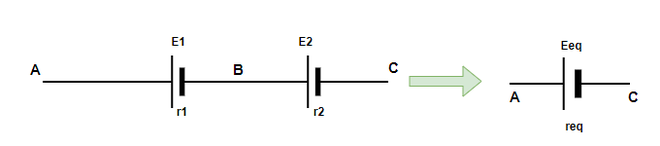
VAB = V(A) – V(B) = E1 – Ir1
VBC = V(B) – V(C) = E2 – Ir2
Thus, the potential difference between the points A and C will be given by,
V(A) – V(C) = [V(A) – V(B)] – [V(C) – V(B)]
⇒ V(A) – V(C) = E1 + E2 – (Ir1 + Ir2)
⇒ V(A) – V(C) = E1 + E2 – (Ir1 + Ir2)
To replace this combination of cells with a single equivalent cell of emf value Eeq and req. Then,
⇒ Eeq – I(req) = E1 + E2 – (Ir1 + Ir2)
Eeq = E1 + E2 and req = r1 + r2
This can be extended to any number of cells, Eeq = E1 + E2 + … and req = r1 + r2 + …
In this case, connected the negative electrode of the battery are connected to the positive electrode of another battery. In case we connect their similar electrodes together, the two emf’s will now point in opposite directions. In that case, the equivalent values will be,
E = E1 – E2 + … and req = r1 + r2 + …
Parallel Combination of Cells
The figure below describes a parallel combination of batteries, in this combination cells are connected in parallel. E1 and E2 are the emf’s of two cells and r1, r2 are their internal resistances. This time, the current flowing through each cell is different and they are denoted by I1 and I2 while the total current flowing through the circuit is denoted by I and is the sum of both of the two currents.
I = I1 + I2
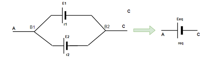
Let V(B1) and V(B2) denote the potential at B1 and B2. Consider both the cells one by one,
V = V(B1) – V(B2) = E1 – I1R
V = V(B1) – V(B2) = E2 – I2R
I = I1 + I2
Rearranging the equation to take out the value of V,
To replace this combination of cells with a single equivalent cell of emf value Eeq and req. Then,
Advantages of Cells Connected in Parallel
- Damage to one cell in a parallel connection does not impact the other cells.
- Cells connected in parallel tend to have a longer lifespan without depleting quickly.
Disadvantages of Cells Connected in Parallel
- Adding more cells in parallel won’t boost the developed voltage.
- The brightness of the connected bulb relies on a single cell, so don’t expect it to be very bright even with multiple cells.
Sample Problems on Parallel Combination of Cells
Question 1: Batteries of 10V and 5 V are connected in series such that their emf’s point in the same direction. Find the equivalent resistance for the system.
Answer:
The formula for equivalent series emf is given by,
Eeq = E1 + E2 + …
Given: E1 = 10, E2 = 5
Substituting these values in the equation,
E = E1 + E2
⇒ E = 10 + 5
⇒ E = 15 V
Question 2: Batteries of 3, 5, and 10 ohms are connected in series such that their emf’s point in the same direction. Find the equivalent resistance for the system.
Answer:
The formula for equivalent series emf is given by,
Eeq = E1 + E2 + …
Given: E1 = 3, E2 = 5and E3 = 10
Substituting these values in the equation,
E = E1 + E2 + E3
⇒ E = 3 + 5 + 10
⇒ E = 18 V
Question 3: Batteries of 10V and 5 V are connected in series such that their emf’s point in the same direction. The internal resistances of the batteries are 2 and 10 ohms respectively. Find the equivalent resistance for the system.
Answer:
The formula for equivalent series emf is given by,
Eeq = E1 + E2 + …
Given: E1 = 10, E2 = 5
Substituting these values in the equation,
E = E1 + E2
⇒ E = 10 + 5
⇒ E = 15 V
Equivalent resistance is also given by a similar equation,
req = r1 + r2 +
Given: r1 = 2, r2 = 10
substituting these values in the equation,
r = r1 + r2
⇒ r = 2 + 10
⇒ r = 12 ohms
Question 4: Three batteries of internal resistances 2, 2, and 4 ohms are connected in parallel. Find the equivalent resistance for the system.
Answer:
The formula for equivalent resistance is given by,
Given: R1 = 2, R2 = 2 and R3 = 4
Substituting these values in the equation,
⇒
⇒
⇒
Question 5: Three batteries of internal resistances 5, 5 ohm, and 10, 10 V are connected in parallel. Find the equivalent resistance and emf for the system.
Answer:
The formula for equivalent resistance is given by,
Given: R1 = 5, R2 = 5
Substituting these values in the equation,
⇒
⇒
The equivalent emf is given by,
⇒
⇒
⇒ Eeq = 10 V
Kirchhoff’s Laws
Kirchhoff’s Laws are the basic laws used in electrostatics to solve complex circuit questions. Kirchhoff’s Laws were given by Gustav Robert Kirchhoff who was a famous German Physicist. He gave us two laws Kirchhoff’s Current Law and Kirchhoff’s Voltage Law which are discussed in this article.
These laws deal with the flow of current and the voltage applied in the complex circuit and provide a way to solve these complex circuits. In this article, we will learn about Kichhoff’s Current Law, Kirchhoff’s Voltage Law, their applications, examples, and others in detail.
History of Gustav Robert Kirchhoff
Gustav Robert Kirchhoff was a German physicist who was born in Prussia a state under German Empire on 12 March 1824. He gave his contribution to the field of electrical circuits, black body radiation, and spectroscopy. He was the one who coined the term ‘Black Body Radiation’. Kirchhoff’s Circuit Law is the combination of Kirchhoff’s Voltage Law (KVL) and Kirchhoff’s Current Law (KCL) which were published in 1845 as part of his doctoral dissertation.
The image added below shows the Gustav Robert Kirchhoff

Circuit analysis is carried out using these laws. They are helpful in the calculation of current flow and voltage flow in various streams across the network.
Kirchhoff’s Laws Definition
Kirchhoff’s Laws are the basic laws used in circuit analysis to solve complex circuit problems. Gustav Robert Kirchhoff gave us two laws Kirchhoff’s Voltage Law (KVL) and Kirchhoff’s Current Law (KCL) which are widely used in circuit analysis. Kirchhoff’s Voltage Law (KVL) is based on the conservation of energy, whereas Kirchhoff’s Current Law (KCL) is based on the conservation of charge. These laws help us to calculate the resistance or impedance connected to the circuit and the current flowing through them.
Different Names of Kirchhoff’s Laws
- Kichhoff’s Current Law is often called Kirchhoff’s First Law or Kirchhoff’s Junction Rule
- Kirchhoff’s Voltage Law is often called Kirchhoff’s Second Law or Kirchhoff’s Loop Rule
Kirchhoff’s Current Law or Kirchhoff’s First Law
Kirchhoff’s Current Law states that
“The total current or charge entering a junction or node is precisely equal to the total current or charge exiting the node, as no charge is lost at the node”.
To put it another way, the algebraic sum of all currents entering and exiting a node must be zero. Kirchhoff’s Current Law (KCL) is also known as Kirchhoff’s First Law or Kirchhoff’s Junction Rule.
Note:
Kirchhoff’s First law is similar to the Law of Conservation of charge. As a result, a Node or junction is a point in a circuit that does not serve as a charge source or sink.
Therefore,
n∑k=1 IK = 0
Where n denotes the total number of branches at the node with currents flowing toward or away from it.
i.e.
I(exiting)+I(entering) = 0
For Example,
In the figure shown below the node or the junction has five branches. The three incoming currents, i3, i4, and i5, and the two incoming currents, i1 and i2. Hence, According to Kirchhoff’s Current Law, the sum of total incoming and outgoing currents at the node will now equal zero. Consider the current entering the node as positive and the current exiting the node as negative then the algebraic sum can be represented as
(-I1) + (-I2) + (I3) + (I4) + (I5) = 0
⇒ I3 + I4 + I5 = I1 + I2

It should be kept in mind that individual currents are not necessarily the same but the sum of currents entering and exiting are the same. It should be noted that there are no set rules for assigning positive and negative signs to the current. However, to avoid confusion entering current is taken as positive, and exiting current is taken as negative.
Kirchhoff’s Voltage Law or Kirchhoff’s Second Law
Kirchhoff’s Second Law states that
The voltage drop around a loop equals the algebraic sum total of the voltage drop across every electrical component linked in the same loop for any closed network and is equal to zero.
Note
Kirchhoff’s Second Law is similar to the Law of Conservation of energy. Because the net change in the energy of a charge after it completes a closed route must be zero.
For Example,
Consider a section of a resistor network with an internal closed loop, as seen in the diagram given below. In the closed loop, we wish to write the voltage change. The total of all voltage drops between the components (mentioned as R) linked in the loop PQRSP is zero, According to Kirchhoff’s Voltage Law.
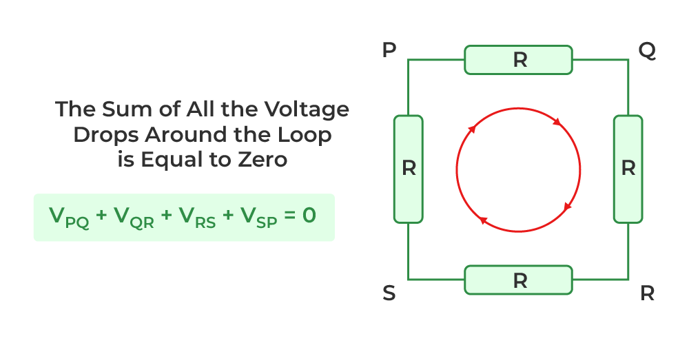
So for a closed loop,
n∑k=1 Vk=0
The total number of electrical components in the loop is given by n.
i.e.
VPQ + VQR + VRS + VSP = 0
How to Apply Kirchhoff’s Laws
When using Kirchhoff’s Current Law, the currents exiting a junction must be considered negative, while the currents entering the junction must be considered positive.
Also, while using Kirchoff’s Voltage Law, we keep the same anti-clockwise or clockwise orientation from the beginning of the loop and account for all voltage decreases as negative and increases as positive. This brings us back to the initial point when the total voltage loss is zero.
Sign Conventions for Kirchhoff’s Law
Use the following convention to assign sign in the circuit provided
- Take Positive sign for current entering the junction and negative for current leaving the junction
- In a loop, a rise in potential difference or EMF from lower to higher is always seen as positive i.e. moving from negative to positive terminal
- In a loop, a reduction in potential difference or EMF from higher to lower is always seen as negative i.e. moving from positive to negative terminal.
- If the looping direction is the same as the current flowing through the circuit, the voltage drop across the resistor is considered negative.
Uses of Kirchhoff’s Law
Kirchhoff’s Law is used for following
- It is used to find out how much current is flowing and how much voltage is dropped in various areas of the complicated circuit.
- It aids in determining the direction of current in various circuit loops.
- Kirchhoff’s Laws can help you comprehend how energy moves via an electric circuit.
Limitations of Kirchhoff’s Laws
There are various limitations associated with Kirchhoff’s Laws which are:
- Kirchhoff’s Law has one fundamental flaw: it implies that there is no changing magnetic field throughout the loop’s region, which might induce a change in magnetic flux and the creation of EMF in the circuit. This might result in a calculation mistake for high-frequency AC circuits.
- Kirchhoff also ignored the impact of the electric field generated by other circuit components.
- Kirchhoff’s Current Law works with the premise that current only travels through conductors and wires. While parasitic capacitance can no longer be overlooked in High-Frequency circuits. Because conductors or wires are serving as transmission lines in certain circumstances, electricity may start flowing in an open circuit.
Kirchhoff’s Law Solved Examples
Example 1: Find the value of I from the circuit in the figure below.
.png)
Solution:
Apply Kirchhoff’s First Law to the point P in the supplied circuit.
Consider the sign convention: positive arrows point toward P, whereas negative arrows point away from P.
As a result, we now have the following:
0.2 A – 0.4 A + 0.6 A – 0.5 A + 0.7 A – I = 0
1.5 A – 0.9 A – I = 0
0.6 A – I = 0
I = 0.6A
Example 2: Find the value of the current passing through the resistance R1 = 10 Ω in the circuit below using Kirchhoff’s principles, when R2 and R3 both are equal and their value is 5 Ω.
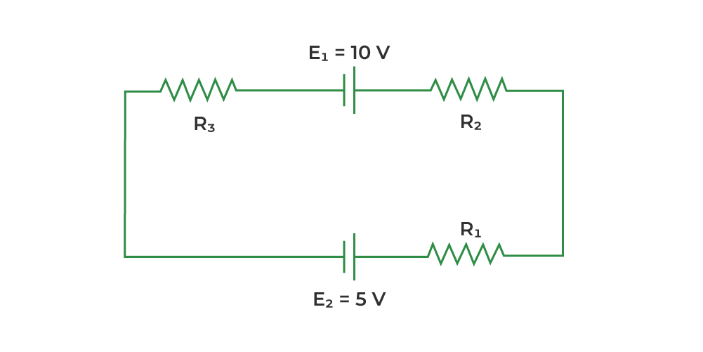
Solution:
Applying Kirchhoff’s Law in the above circuit, Let’s take the current ‘i’ passing through the loop in the clockwise direction
-10 + 5(i) + 5(i) + 10(i) + 5 = 0
20i -5 = 0
20i = 5
i = 5 / 20 =1/4
The current passing through R1 is 1/4 Ampere.
Also, Check
FAQs on Kirchhoff’s Law
Q1: Who gave Kirchhoff’s Laws?
Answer:
Kirchhoff’s law was discovered by a German Physicist, Gustav Robert Kirchhoff
Q2: What is Kirchhoff’s Voltage Law?
Answer:
Kirchhoff’s Second Law also called Kirchhoff’s Voltage Law states that ” For any closed network Voltage around a loop is equal to the sum of voltage drop in the same loop and it is equal to zero.”
Q3: What is Kirchhoff’s Current Law?
Answer:
Kirchhoff’s First Law also called Kirchhoff’s Current Law states that ” Total current entering in a junction is equal to the total current leaving that junction.”
Q4: Kirchhoff’s Second Law is also known as?
Answer:
Kirchhoff’s second law is also known as Kirchhoff’s Voltage Law.
Q5: How many Kirchhoff Laws are there?
Answer:
There are two Kirchhoff laws
- Kirchhoff’s First Law or Kirchhoff’s Current Law
- Kirchhoff’s Second Law or Kirchhoff’s Voltage Law
Q6: Why does Kirchhoff’s Law Fail at High Frequency?
Answer:
Because the rules KCL and KVL are incompatible with high-frequency AC circuits, Kirchhoff’s laws fail at high frequencies. At higher frequencies, the interference of induced EMF caused by changing magnetic fields becomes more severe.
Wheatstone Bridge
Wheatstone bridge is a device that is used to find the resistance of a conductor, in 1842, scientist Wheatstone proposed a theory, which is called the principle of Wheatstone bridge after his name. we can prove or establish the formula for Wheatstone by using Kirchhoff laws. Wheatstone bridge is simply an electric circuit used to measure an unknown electric resistance by balancing two-point of a bridge. Let’s get started!
Wheatstone Bridge Definition
Wheatstone Bridge is an instrument designed to measure unknown resistance in electrical circuits. It calculates the unknown resistance by balancing the two legs of the bridge circuit where one leg contains both known resistors and the other leg contains one known (variable) and one unknown resistor. Since it estimates unknown resistance in an electric circuit, it is also known as a resistance bridge. Wheatstone bridge is a very reliable instrument as it measures the resistance very precisely.
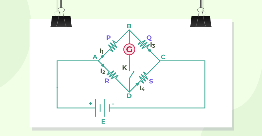
Wheatstone Bridge Principle
Wheatstone Bridge works on the principle of null deflection i.e., there is no current flowing through the galvanometer, and its needle shows no deflection, hence the name null deflection. In the unbalanced state of the Wheatstone bridge i.e., when the potential across the galvanometer is different, the galvanometer shows the deflection, and as the bridge becomes balanced by changing the variable resistor, the potential difference across the galvanometer becomes zero i.e., the equilibrium state of Wheatstone bridge.
Construction of Wheatstone Bridge
Construction of Wheatstone Bridge requires four resistors P, Q, R, and S that are placed in the form of four sides AB, BC, AD, and DC of a quadrilateral ABCD. A cell E and key K1 are placed between the A and C ends of this quadrilateral, and a sensitive galvanometer G and key K2 is placed between the B and D ends. Clearly, the potential of point A will be equal to the potential of the positive plate of the cell and the potential of point C will be equal to the potential of the negative plate of the cell.
It is clear from the figure that the resistances P and Q are in series when the key K2 is open. Similarly, resistances R and S are in series, but P and Q together (arm ABC) and R and S together (arm ADC) are connected in parallel to each other. Since the side BD of the galvanometer is placed like a bridge over the sides ABC and ADC of the quadrilateral, this circuit is called a bridge.
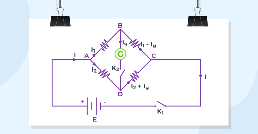
When the bridge is in an equilibrium state, that is, there is no deflection in the galvanometer. That is, in the equilibrium state of the bridge, the ratio of the resistances of any two adjacent arms is equal to the ratio of the remaining two adjacent sides. 
Wheatstone Bridge Derivation
Suppose, on pressing the cell key K1, a current I flows through the cell, which splits into two parts at the end A. One part I1 flows through the resistance P in arm AB and the other part I2, through the resistance R in arm AD. The current I1 again comes to end B and gets divided into two parts. One part of it Ig flows through the galvanometer in arm BD and the remaining part (I1– Ig) flows through resistance Q in arm BC. At the end D, the current I2 from arm AD and the current Ig from arm BD, so the current flowing through the resistance S in arm DC will be (I2 + Ig).
So according to Kirchhoff’s law, in closed path ABDA,
I1P + IgG – I2R = 0 . . . (1)
And in closed path BCDB,
(I1 – Ig)Q – (I2 + Ig)S – IgG = 0 . . . (2)
The values of the resistors P, Q, R, and S are taken in such a way that no current flows through the galvanometer G when the key K2, is pressed. This is called the equilibrium state of the bridge, that is, in the equilibrium state of the bridge, the deflection in the galvanometer is zero (Ig = 0).
Putting Ig = 0, in the above equations,
I1P = I2R and I1Q = I2S
or
I1P / I1Q = I2R / I2S
or
P / Q = R / S
This is the necessary condition for the balance of the Wheatstone Bridge. With the help of the above formula, knowing the values of three resistors P, Q, and R, the value of the fourth resistance S can be found.
Wheatstone Bridge Formula
The Wheatstone Bridge Formula for the calculation of the unknown resistor is as follows:
R = PS/Q
where,
P and Q is the resistance of ratio arm
S is the known resistance of the standard arm
R is the unknown resistance
Advantages of Wheatstone’s Bridge
Various advantages of the Wheatstone’s Bridge are,
- With the help of Wheatstone’s Bridge, we can build a Meter bridge.
- The biggest advantage of Wheatstone’s Bridge is to accurately measure the electric resistance instead of using costly instruments.
- We can measure minute changes in the bridge, even in m ohm.
- It is very easy to find out the unknown resistance as the rest of the three are easily known.
- We can measure strain and pressure using a Wheatstone bridge.
Disadvantages of Wheatstone’s Bridge
Various disadvantages of the Wheatstone’s Bridge are,
- The result of Wheatstone’s Bridge can be easily affected by temperature and EMF cells.
- Wheatstone bridge may also get affected if the galvanometer is not of good quality.
- Wheatstone Bridge fails if it is not in a balanced condition.
- We can’t measure large resistance with the help of Wheatstone’s Bridge.
- The cost of maintaining the Wheatstone Bridge is very high.
Wheatstone Bridge Applications
Wheatstone Bridge and the modification of Wheatstone Bridge are very useful tools in the field of physics and are used in a variety of measurement use cases, some of which are as follows:
- The most common use of Wheatstone Bridge is to measure resistance, as it can measure resistance very precisely. A Meter Bridge is one of the applications of Wheatstone Bridge, which can measure unknown resistance with the help of everyday materials and a galvanometer.
- With some modifications in Wheatstone Bridge, we can even measure quantities like Capacitance, Inductance, and Impedance.
- Using Wheatstone Bridge and operational amplifiers, we can measure a variety of physical parameters such as temperature strain, light, etc.
Wheatstone Bridge Limitations
Wheatstone Bridge is one of the best tools but it also has major limitations, which are as follows:
- Wheatstone Bridge is not ideal for very low resistance measurement as the resistance of contact and leads also has some amount of resistance, which can introduce a significant amount of errors in the measurement. Kelvin’s Double Bridge (a modification of Wheatstone Bridge) is used for the measurement of small resistance.
- For High resistance measurements (mega ohms and giga ohms of resistance), the resistance provided by the bridge becomes so high that the galvanometer becomes sensitive to imbalance. So, we can’t use Wheatstone Bridge in case of high resistance measurement.
- The resistance of a conductor depends on the temperature and the heating effect of the current causes the conductor to heat and heat changes the resistance of the conductor. This can introduce errors in the calculation and for excessive amounts of current the error can be very significant. Thus, it is also a flaw in the design of Wheatstone Bridge.
Also, Check
Sample Questions on Wheatstone Bridge
Question 1: Find the equivalent resistance between points A and C in the circuit shown in the figure below:
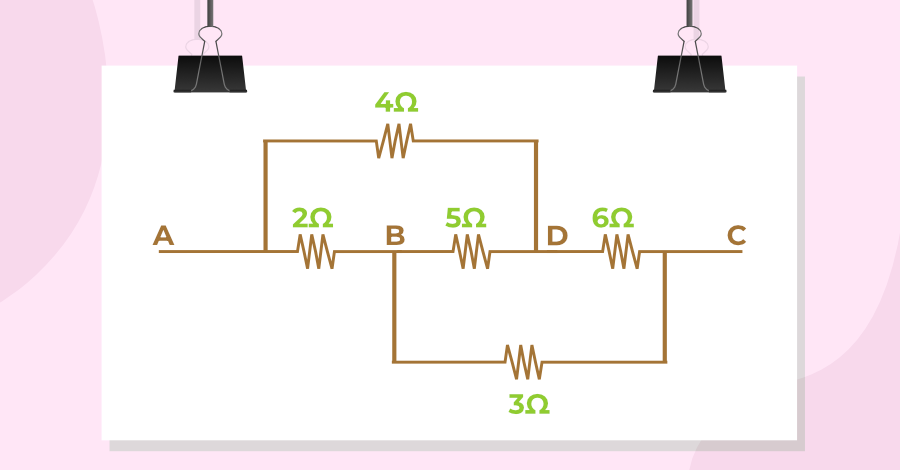
Answer:
The equivalent circuit of the circuit shown in the above figure is given as:
Since, 2/3 = 4/6
This is the circuit of a balanced Wheatstone bridge.
In the balanced state, VB = VD (where V represents potential)
So no current will flow through the 5 Ω resistance.
Now the equivalent resistance of sides AB and BC is R’ = 2 + 3 = 5 Ω.
The equivalent resistance of AD and DC arm R” = 4 + 6 = 10 Ω
If the equivalent resistance between the points A and C is R, and R is parallel combination of resistance R’ and R”,
⇒ 1 / R = (1 / R’) + (1 / R”)
⇒ 1/R = (1/5) + (1/10)
⇒ 1/R = (2 + 1) / 10
⇒ R = 10/3
⇒ R = 3.33 Ω

Question 2: The electric circuit of a balanced Wheatstone bridge is shown in Figure. Calculate the resistance x.
Answer:
Let the total resistance in arm BC be R. Since the bridge is balanced, therefore:
15/R = 5/10
⇒ R = (15 × 10)/5 = 30 Ω
Now, as R is parallel combination of 60 Ω and X.
⇒ 1/R = (1/X) + (1/60)
⇒ 1/30 = 1/X + (1/60)
⇒ 1/X = 1/30 – 1/60
⇒ 1/X = (2 – 1)/60 = 1 / 60
⇒ X = 60 Ω

Question 3: What is a Meter Bridge and what kind of precautions do we need to perform measurements using a Meter Bridge?
Answer:
A Meter bridge is a device based on the principle of the Wheatstone bridge, with the help of which the resistance and specific resistance of a conductor can be determined. In this, a 1-meter long wire acts as the proportional side.
Precautions while using Meter Bridge are:
- The ends of all the connection wires should be cleaned with sandpaper.
- The current should not flow in the circuit for a long time otherwise, its resistance increases due to the heating of the bridge wire. Therefore, the key in the cell circuit should be plugged in only when observations are to be made.
- The jockey should not be run by rubbing it on the meter bridge wire otherwise, the thickness of the wire will not remain the same at all places.
- A shunt with a galvanometer should be used initially while adjusting, but the shunt should be removed near the position of zero deflection.
- Only such a resistance plug should be removed from the resistance box so that the position of zero deflection is approximately in the middle of the bridge wire. In this case, the sensitivity of the bridge is maximum and the percentage error is minimum.
- All other plugs in the resistance box, except those that have been removed, should be tightly packed.
Question 4: In the following figure, find the current through the 4Ω resistor.

Answer:
Since, Q / P = S / R
⇒ 4 / 20 =10 / 50
It is an example of balanced wheat-stone bridge.
So, No current will flow through 16 Ω resistance.
As we know that current divide in inverse ratio, current through 4Ω resistance is,
= 1.4 × (20+4)+(50+10) / (50+10)
= 1.4 × (7/5)
= 1 A
FAQs on Wheatstone Bridge
Q1: What is Wheatstone Bridge?
Answer:
A circuit is designed for the measurement of an unknown resistance by connecting three known and one unknown resistance in the form of a quadrilateral, and a voltage is applied to the opposite corners of the quadrilateral. This is known as the Wheatstone Bridge.
Q2: What is the principle of Wheatstone Bridge?
Answer:
The Wheatstone Bridge works on the principle of null deflection, where the ratio of the resistance is equal and no current flows through the galvanometer.
Q3: What is the balanced condition of the Wheatstone Bridge?
Answer:
When no current flows through the galvanometer and it shows no deflection, the Wheatstone Bridge is said to be in a balanced condition. This condition is also called the equilibrium condition as well.
Q4: When is Wheatstone Bridge most sensitive?
Answer:
When all four resistances in the wheatstone bridge are almost equal, then the wheatstone bridge is said to be most sensitive.
Q5: Which instrument is used as a null detector in Wheatstone Bridge?
Answer:
The galvanometer is used as a null detector in the Wheatstone Bridge, where a null point is the condition where no current passes through the circuit where the galvanometer is connected.
0 Comments