
CBSE Class 12 Physics Notes Chapter 2 – Electrostatic Potential and Capacitance
The second chapter of electrostatic is about Electrostatic Potential and Capacitance, which is the continuation of the first chapter and extends the foundational knowledge of electrostatics to the dimension of potential, which in very simple terms is the accumulation of charges. A list of all the other things than Potential which students study in this chapter is as follows:
- Electrostatic Potential
- Potential Due to a Point Charge
- Potential Due to an Electric Dipole
- Potential Due to a System of Charges
- Equipotential Surfaces
- Potential Energy of a System of Charges
- Potential Energy in an External Field
- Electrostatics of Conductors
- Dielectrics and Polarisation
- Capacitors and Capacitance
- The Parallel Plate Capacitor
- Effect of Dielectric on Capacitance
- Combination of Capacitors
- Energy Stored in a Capacitor
Electric Potential Energy
Electrical potential energy is the cumulative effect of the position and configuration of a charged object and its neighboring charges. The electric potential energy of a charged object governs its motion in the local electric field.
Sometimes electrical potential energy is confused with electric potential, however, the electric potential at a specific point in an electric field is the amount of work required to transport a unit charge from a reference point to that specific point and electrical potential energy is the amount of energy required to move a charge against the electric field.
In this article, let’s understand the electrical potential energy, electric potential, their key concepts, applications, and solved problems.
Table of Content
- What is Electric Potential Energy?
- Electric Potential Energy Formula
- Electric Potential Energy of a Point Charge
- Electric Potential Energy of a System of Charges
- What is Electric Potential?
- What is Electric Potential Difference?
- Electric Potential Derivation
- Electric Potential of a Point Charge
- Solved Examples on Electric Potential Energy
What is Electric Potential Energy?
The electric potential energy of a system of charges or a single charge is the total work done by an external force to bring the charge or system of charges from infinity to a reference point in an electric field without any acceleration.
Definition: Electric potential energy is the total energy possessed by a charge in order to change its position in the electric field.
Electric Potential Energy Overview
As electrical potential energy has only magnitude and no direction, therefore it is a scalar quantity. The SI unit of electric potential energy is Joule (J). The following table shows some important points and symbols of the electric potential energy:
Electric Potential Energy | |
| Representation | UE or U |
| Dimensions | ML2T-2 |
| General Formula | UE = kq1q2/r |
| SI Unit | Joules |
Two factors are majorly responsible for the electric potential energy:
- The charge on the object.
- The relative position of the object with another neighboring charge.
Electric Potential Energy Formula
If W is the work done in transferring a unit positive charge q from infinity to a particular point in the electric field, this work done energy will be stored in form of the electric potential energy or electrostatic potential energy.
Let’s derive the expression for electric potential energy,
Consider the electrostatic field E that exists as a result of a charge arrangement. Consider the electric field E caused by a charge Q placed at the origin for simplicity.
Consider moving a test charge q from a point R to a point P while resisting the charge Q’s repulsive force. If Q and q are both positive or both negative, this will happen with reference. Let’s use Q as an example, with q > 0,
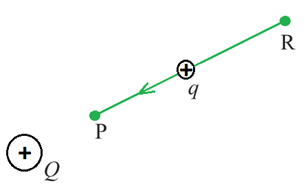
A test charge q (> 0) is moved from point R to point P against the repulsive force on it by the charge Q (> 0) placed at the origin.
Assume that the test charge q is so little that it has no effect on the original configuration, specifically the charge Q at the origin (or that Q is held fixed at the origin by some unknown force). Second, apply an external force Fext exactly enough to counter the repulsive electric force FE (i.e. Fext= –FE ) as the charge q move from R to P.
This means that when the charge q is transported from R to P, it experiences no net force or acceleration, implying that it is transported at an infinitesimally slow constant speed. In this case, the work done by the external force is minus the work done by the electric force, and the potential energy of the charge q is fully stored.
If the external force is withdrawn when the charge reaches P, the electric force will pull the charge away from Q – the stored energy (potential energy) at P is used to provide kinetic energy to the charge q, preserving the sum of the kinetic and potential energies.
Therefore, the work done by external forces in moving a charge q from R to P can be written as,

Since, Fext= –FE, then we can write,

The above expression is the work done against electrostatic opposing force and gets stored as potential energy. A particle with charge q has a definite electrostatic potential energy at every location in the electric field.
The work done raises its potential energy by an amount equal to the potential energy difference between points R and P. Therefore, the potential energy difference can be expressed as,
∆U = UP – UR = WRP
Note that this displacement is in the inverse direction of the electric force, hence the work done by the electric field is negative, i.e., –WRP.
As a result, the work required by an external force to move (without accelerating) charge q from one location to another for an electric field of any arbitrary charge configuration can be defined as the electric potential energy difference between two points. At this point, two key points should be made,
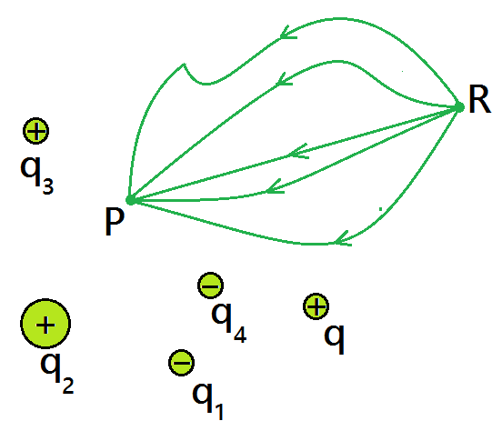
- The work done by an electrostatic field in transferring a charge from one location to another is solely reliant on the initial and final points and is unaffected by the path used to get there. This is a conservative force’s defining attribute.
- The above expression defines the difference in potential energy in terms of a physically meaningful quantity of work. Within an additive constant, potential energy is clearly uncertain.
- This indicates that the actual value of potential energy has no physical significance; only the change in potential energy is essential. We can always add an arbitrary constant to potential energy at any time since the potential energy difference will not change,
(UP – β ) – (UR – β ) = UP – UR
To put it another way, the point where potential energy is zero can be chosen at will. Electrostatic potential energy 0 at infinity is a convenient choice. If we take the point R at infinity with this option,
W∞P = UP – U∞ = UP – 0 = UP
The above expression defines the potential energy of a charge q at any moment in time.
The work done by the external force (equal and opposite to the electric force) in bringing the charge q from infinity to that location (in the presence of field due to any charge configuration) is called potential energy of charge q at a point.
Electric Potential Energy of a Point Charge
Consider the origin of a point charge Q. Consider Q to be a positive character. We wish to find the electrical potential energy at any location P using the position vector r from the origin. To do so, we need to figure out how much work it takes to transfer a unit-positive test charge from infinity to point P.
When Q > 0, the work done against the repulsive force on the test charge is positive. Because the work is independent of the path, we choose a convenient path, i.e., along the radial direction from infinity to point P.
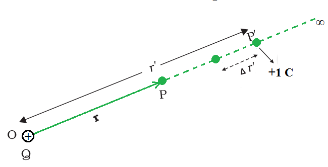
Work done in bringing a unit positive test charge from infinity to the point P, against the repulsive force of charge Q (Q > 0), is the potential at P due to the charge Q.
The electrostatic force on a unit positive charge at some intermediate point P′ on the path equals to

where  is the unit vector along OP’, therefore, work done against this force from r′ to r′ + ∆r′ can be written as

The negative sign represents ∆r′ < 0, and ∆W is positive. Total work done (W) by the external force is determined by integrating the above equation on both sides, from r′ = ∞ to r′ = r,
![W=-\int_{∞}^{r} \frac{Q}{4\pi\epsilon_0r'^2}d{r'}\\ W=\left[\frac{Q}{4\pi\epsilon_0r'}\right]_∞^r\\ W=\frac{Q}{4\pi\epsilon_0r}](https://www.geeksforgeeks.org/wp-content/ql-cache/quicklatex.com-d2e0180c3df582bd6cbe1919ff24155a_l3.svg "Rendered by QuickLaTeX.com")
The potential at P due to the charge Q can be expressed as,

Electric Potential Energy of a System of Charges
Potential at a point due to a system of charges is the sum of potentials due to individual charges.
Suppose a system of charges q1, q2,…, qn with position vectors r1, r2,…, rn relative to some origin. The potential V1 at P due to the charge q1 can be expressed as

Where r1P is the distance between q1 and P.
Similarly, the potential V2 at P due to q2 and V3 due to q3 can be written as,

where r2P and r3P are the distances of P from charges q2 and q3, respectively, and so on for the potential due to other charges.
By the superposition principle, the potential V at P due to the total charge configuration is the algebraic sum of the potentials due to the individual charge, that is,
V = V1 + V2 + V3 +…. + Vn
The above expression can be expressed as,


It is necessary to divide a continuous charge distribution with a charge density (r) into small volume elements of size ∆v, each carrying a charge ρ∆v. Then, for each volume element, compute the potential and add (or, more properly, integrate) all of these contributions to get the overall potential owing to the distribution.
What is Electric Potential?
The electric potential is defined as the amount of energy required to bring a unit mass object from a reference point to a specific point. If W amount of work is done to move an object of charge q from a point A to a reference point B. The formula for the electric potential can be expressed as,

where VB and VA are the electric potentials at points B and A, respectively.
In general, think about any static charge configuration. A test charge’s potential energy q is defined in terms of the work done on it.
This work is obviously proportional to q because the force at any position is qE, where E is the electric field at that site due to the given charge arrangement. As a result, dividing the work by the charge q yields a quantity independent of q.
The work done by an external force to carry a unit positive charge from infinity to a specific location is equal to the electrostatic potential (V) at that point.
In other words, the electrostatic potential (V ) at any place in an area with an electrostatic field is the work needed to transport a unit positive charge from infinity to that specific location (without acceleration).
Electric potential is a scalar quantity with no direction and only magnitude. It is symbolized by V and has the dimensional formula ML2T-3A-1.
Work done on a test charge q by the electrostatic field due to any given charge configuration is independent of the path and depends only on its initial and final positions
The same caveats that were expressed before about potential energy apply to the definition of potential.
To calculate the work done per unit test charge, start with an infinitesimal test charge δq, calculate the work done δW in bringing it from infinity to the point, and divide by δq to get the δW/δq ratio. In addition, at each point along the path, the external force must be equal to and opposite to the electrostatic force acting on the test charge.
Check: Magnitude of Vector
What is Electric Potential Difference?
Electric potential difference is also known as voltage.
The electric potential difference is the work done per unit charge to move a unit charge from one point to another in an electric field.
Electric potential difference is usually referred to as a Voltage difference. Imagine a ball sitting at some height, will there be some energy in the ball? Yes, the energy is called Potential energy, and if the ball is dropped from a point A to B height, the ball will always fall from higher gravitational potential to lower, then there will be a difference in both energies.
The electrical potential difference is analogical to this concept. The energy possessed by Electric charges is known as electrical energy.
A charge with higher potential will have more potential energy, and a charge with lesser potential will have less potential energy.
The current always moves from higher potential to lower potential. The formula for electric potential difference:
Vxy = Vx – Vy = [Wx – Wy]/q
Electric Potential Derivation
Let’s contemplate a charge, denoted as q1 positioned at a distance ‘r’ from another charge. The overall electric potential of this charge is characterized as the cumulative work accomplished by an external force in transporting the charge from an infinite distance to the specified location.
We can write it as, -∫ (ra→rb) F.dr = – (Ua – Ub)
Here, we see that the point rb is present at infinity, and the point ra is r.
Substituting the values, we can write, -∫ (r →∞) F.dr = – (Ur – U∞)
As we know that Uinfity is equal to zero.
Therefore, -∫ (r →∞) F.dr = -UR
Using Coulomb’s law between the two charges, we can write:
⇒ -∫ (r →∞) [-kqqo]/r2 dr = -UR
Or, -k × qqo × [1/r] = UR
Therefore, UR = -kqqo/r
Electric Potential of a Point Charge
Let’s contemplate a scenario where a point charge ‘q’ exists alongside another charge ‘Q’, with an infinite distance separating them.
UE (r) = ke × [qQ/r]
where, ke = 1/4πεo = Columb’s constant
Let us consider a point charge ‘q’ in the presence of several point charges Qi with infinite separation between them.
UE (r) = ke q × ∑ni = 1 [Qi /ri]
Related Links:
Solved Examples on Electric Potential Energy
Example 1: Suppose you have a 12.0 V motorcycle battery that can move 5000 C of charge and a 12.0 V car battery that can move 60,000 C of charge. How much energy does each deliver?
Solution:
Given,
The voltage of the battery is V =12.0 V.
The charge that the motorcycle battery move is Q = 5000 C.
The 12.0 V car battery can move 60,000 C of charge.
When such a battery moves charge, it puts the charge through a potential difference of 12.0 V, and the charge is given a change in potential energy equal to Δ(PE) = qΔV.
For the motorcycle battery, q = 5000 C and ΔV = 12.0 V. The total energy delivered by the motorcycle battery is
ΔPEmotorcycle = (5000 C) × (12.0 V)
ΔPEmotorcycle = 6.00 × 10⁴ J
Now, for the car battery,
ΔPEcar = (60,000 C) × (12.0 V)
ΔPEcar =7.20 × 10⁵ J
Example 2: A particle of mass 40 mg carrying a charge 5 × 10⁻⁹ C is moving directly towards a fixed positive point charge of magnitude 10-8 C. When it is at a distance of 10 cm from the fixed point charge, it has a velocity of 50 cm/s. At what distance from the fixed point charge will the particle come momentarily to rest? Is the acceleration constant during motion?
Solution:
Given,
The mass of the particle m = 40 mg.
The charge of the particle Q = 5×10⁻⁹ C.
The fixed positive point charge of magnitude q =10-8 C.
Velocity of the charged particle is v = 50 cm/s = 0.5 m/s
The particle comes to rest momentarily at a distance r from the fixed charge, from conservation of energy we have,
According to the law of conservation of energy, the total energy of the system = Constant
i.e., (K.E. + P.E.) = constant.
The expression for the kinetic energy can be expressed as,

The expression for the potential energy can be expressed as,
Now,
(1/2)mu2 + (1/4πεo) × [Qq/a] = (1/4πεo) × [Qq/r]
(1/2)mu2 = (1/4πεo) [Qq/r – Qq/a]
(1/2)mu2 = (1/4πεo) Qq[1/r – 1/a]
Substituting the values in the above equation,
1/2 × 40 × 10-6 × (0.5)2= 9 × 109 × 10-8 × 5 × 10-9 × [ 1/r – 1/(10 × 10-2)]
or, [1/r – 10] = (5×10⁻⁵)/(9×5×10-8) = 100/9
or, 1/r = (100/9) + 10
or, 1/r = 190/9 m
or r = 4.7 × 10⁻² m
Since, F = [1/4πεo] × [Qq/r2]
Therefore, acceleration = F/m ∝ 1/r2 , i.e., acceleration is not constant during motion.
Example 3: A ball of mass 5 g and charge 10-7 C moves from point A, whose potential is 500 V, to point B, whose potential is zero. What is the velocity of the ball at point A if at point B, it is 25 cm per second?
Solution:
Given,
The mass ball is 5 g.
The charge of the particle is 10-7 C.
The potential of ball at point A is 500 V and potential at point B is zero.
Suppose u be the velocity of the ball at point A.
The work done on the charge by the field given by,
W = q × (VA – VB)
Substitute the value in the above expression,
W = 10-7 C× (500 V – 0 V)
W = 5 × 10⁻⁵ J
Therefore,
W = (1/2) mv2 – (1/2) mu2
5 × 10⁻⁵ J= (1/2) × (5/1000 )×[(1/4)2 – u2]
2 × 10-2 = 1/16 – u2
u2 = (1/16) – 0.02
u2 = (1- 0.32)/16
u2 = 0.0425
Therefore, u =0.206 m/s
u = 20.6 cm/s.
Example 4: When a 12.0 V car battery runs a single 30.0 W headlight, how many electrons pass through it each second?
Solution:
The expression for the potential energy can be written as,
Δ(PE) = qΔV
Rearrange the above expression,
q = Δ(PE)/ΔV
Substitute the values in the above equation,
q = −30.0 J/ 12.0 V
q = −30.0 J/ 12.0 J/C
q = −2.50 C
The number of electrons n can be calculated as,
n = q/e
n = −2.50 C/(−1.60 × 10−19 C/e)
n = 1.56 × 10¹⁹ electrons
Example 5: How much work is required to be done in order to bring two charges of magnitude 3 C and 5 C from a separation of infinite distance to a separation of 0.5 m?
Solution:
Given,
Two charges of magnitude 3 C and 5 C.
The separation between two charges are 0.5 m.
The potential at P due to the charge Q can be expressed as
∆U = U0 – Ur
∆U = 0 J – [-(9 × 10⁹ Nm2/C2× 5 C × 3 C)/0.5 m] J = 2.7 × 10¹¹J.
Therefore, ∆U = 2.7 × 10¹¹ J.

Conclusion of Electric Potential Energy
Electric potential energy is a cornerstone concept in electromagnetism, representing the stored energy within a system of charges due to their positions relative to each other within an electric field. Defined as the work required to assemble a collection of charges from infinity to their respective positions, electric potential energy depends on the configuration of charges and their distances apart.
Electric Potential Energy – FAQs
What is electric potential energy?
Electric potential energy of a single charge or system of charges is the energy required by an external force in moving a charge in the electric field.
List some examples of electric potential energy.
Some examples of electric potential energy are:
- Air-conditioner system before turning on.
- Vacuum cleaner after turning off.
- Television before turning on.
- Car’s headlights before it is turned on.
What is the electrical potential energy formula?
The formula for electrical potential energy is:
UE = k (q1q2)/r
Where,
- UE = Electric potential energy
- k = Coulomb constant
- q1, q2 = Charges
- r = Distance between charges
How does electric potential energy change with the position of a charge?
The electric potential energy of a charge changes as it moves in an electric field. When a charge moves in the direction of the electric field, its electric potential energy decreases.
What is the significance of zero electric potential energy?
Zero electric potential energy is often assigned to a reference point, typically at infinity, where the electric field is negligible. Charges placed at this reference point have zero potential energy, and any movement towards or away from this point results in a change in potential energy.
How does electric potential energy affect the behavior of charged particles?
Electric potential energy influences the motion of charged particles in an electric field. Charged particles tend to move from regions of higher potential energy to regions of lower potential energy, similar to how objects move from higher to lower gravitational potential energy in a gravitational field.
Can electric potential energy be negative?
Yes, electric potential energy can be negative. This occurs when like charges repel each other, causing work to be done against the electric field. The electric potential energy is negative because the work done is equivalent to a decrease in potential energy.
How is electric potential energy used in practical applications?
Electric potential energy is essential in various practical applications, including electric circuits, electrostatic precipitators, and particle accelerators. Understanding electric potential energy helps engineers design systems for storing, transferring, and manipulating electrical energy.
Electric Potential Due to a Point Charge
Electric forces are responsible for almost every chemical reaction within the human body. These chemical reactions occur when the atoms and their charges collide together. In this process, some molecules are formed and some change their shape. Electric forces are experienced by charged bodies when they come under the influence of an electric field. These forces depend on the direction of the electric field and the charge placed in that field. When charges are moved around in the electric field, these forces do work on the charge and that gets stored in the form of electrostatic potential energy. Let’s look at concepts of electrostatic potential and electrostatic potential energy in detail.
Electric Potential Energy
Electric potential energy is the energy that is required to move a charge against an electric field. When a charge is kept in an electric field, it experiences a force. So, to move against the force, we need to do work and that work gets stored in the charge in the form of electric potential energy. In the figure given below, there is a huge plate that is negatively charged, and it has some positive charges stuck on it.
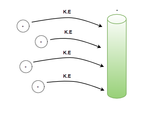
In the figure, when positive charges are separated from the negatively charged plate, they experience force. So, to separate out the charges from the places, work needs to be done against the force that is acting on them. In this process, potential energy is stored in them. When these charges are released, they start running towards the negatively charged plate. So, in this situation, the potential energy stored in these charges is converted into kinetic energy.
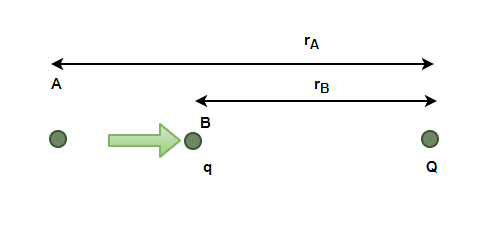
For a two-charge system with charges q and Q given in the figure above, the change in electric potential energy in taking the charge q, from A to B is given by,

Electric Potential
Electric potential is defined as the difference in the potential energy per unit charge between two places. To check the difference in the electric potential between two positions under the influence of an electric field, it is asked, how much the potential energy of a unit positive charge will change if that charge is moved from this position to the other position. Is denoted by V,
V = 
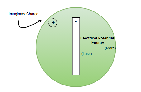
In a similar situation as described in the previous section. The positive charge is near the plate, the farther the charge is from this plate, the more the work done on the charge. So, in this case, we say that the potential near the negatively charged plate is low and as one goes far the potential increases. Now let’s understand the potential due to a point charge in formal terms.
Electric Potential Due to Point Charge
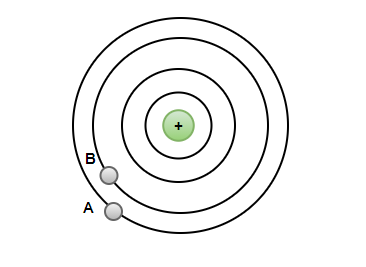
Consider a point charge as shown in the figure below. Notice that in the figure, there are some concentric circles. These concentric circles represent the equipotential contour. That means, that at all the points in a single contour. The potential is the same. The goal is to calculate the electric potential due to this point charge between two points A and B.
Electric potential difference is also called voltage, and it is measured in the units of Volts.
voltageAB = electric potential differenceAB = 
The potential up until now has been defined as a difference; a formulation in terms of absolute potential is required. The above formulation will be modified to come up with this new definition. At infinite, the electric field and the potential are assumed to be zero. Now, the potential at every point will be calculated with respect to the infinite, and it will give an absolute value of the potential.
Now, rB =  and rA
voltageAB =
= 
Now, rB =
= 
= 
Superposition of Electric Potential
For a system of point charges, the total potential at a point is given by the algebraic sum of the potential for individual charges at that point. For example, in a system containing charges Q1, Q2, and Q3 at a distance of r1, r2, and r3 from a point. Then, the potential at this point will be given by the following equation,

Sample Problems
Question 1: Find the potential at a distance of 1 m due to a charge of 2pC.
Answer:
The potential due to a point charge is given by,
Here, q = 2 pC = 2 x 10-12C and r = 1 m.
Plugging the values into this equation,
V =
⇒ V =
⇒ V= 9 × 109 × 2 x 10-12
⇒ V= 18 × 10-3


Question 2: Find the potential at a distance of 0.5 m due to a charge of 10pC.
Answer:
The potential due to a point charge is given by,
Here, q = 10 pC = 10 x 10-12C and r = 0.5m.
Plugging the values into this equation,
V =
⇒ V =
⇒ V= 9 × 109 × 2 x 10-11
⇒ V= 18 x 10-2

Question 3: Find the potential energy at a distance of 0.5 m due to a charge of 10pC and -10pC.
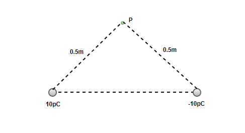
Answer:
The potential due to a point charge is given by,
Here, q1 = 10 pC = 10 x 10-12C, q2 = -10 pC = -10 x 10-12C and r = 0.5m.
Since there are two charges in the system, the total potential will be given by the superposition equation.
For two charges,
Plugging the values into this equation,
⇒ V= 0


Question 4: Find the potential energy at a distance of 2 m due to a charge of 10pC and -2pC.
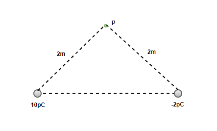
Answer:
The potential due to a point charge is given by,
Here, q1 = 10 pC = 10 x 10-12C, q2 = -10 pC = -2 x 10-12C and r = 2 m.
Since there are two charges in the system, the total potential will be given by the superposition equation.
For two charges,
Plugging the values into this equation,
⇒ V= 36 × 10-3 V

Question 5: Two charges are kept at opposite corners of rectangles as shown in the figure. Find the potential at the corner between them.
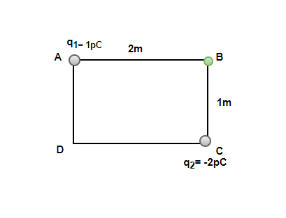
Answer:
The potential due to a point charge is given by,
Here, q1 = 1 pC = 10-12C, q2 = -2 pC = -2 x 10-12C and r1 = 2 m and r2 = 1 m.
Since there are two charges in the system, the total potential will be given by the superposition equation.
For two charges,
Plugging the values into this equation,
⇒ V= 36 × 10-3 V

Electric Potential Of A Dipole and System Of Charges
Electric Potential is defined as the force experienced by a charge inside the electric field of any other charge. mathematically it is defined as the ratio of electric potential energy that is required to take a test charge from infinity to a point inside the electric field of any other charge with the magnitude of the test charge.
Electric potential at any point is determined by the number and orientation of the test charges arranged in their surroundings and their distance from those charges. In this article we will learn about electric potential due to system of charges, its formula, examples and other in detail.
Table of Content
What is Electric Potential?
Electric potential is defined as the difference in the potential energy per unit charge between two places. To check the difference in the electric potential between two positions under the influence of an electric field, we ask ourselves how much the potential energy of a unit positive charge will change if that charge is moved from this position to the other position. It is denoted by V,
V = P.E/q
Electric Potential Due to Point Charge
A point charge is given in the figure below. The concentric circles represent the equipotential. That means, that at all the points in a single surface, the potential is the same. The goal is to calculate the electric potential due to this point charge between two points A and B.
Electric potential difference is also called voltage, and it is measured in the units of Volts.
VoltageAB = Electric potential differenceAB =
The potential has been defined as a difference; a formulation in terms of absolute potential is required. Let’s modify the above formulation to come up with this new definition. At infinite, the electric field and the potential are assumed to be zero. Now, the potential at every point will be calculated with respect to the infinite, and it will give an absolute value of the potential.
Now, rB = ∞ and rA
VoltageAB =
=
Now, rB = ∞
=
=
Electric Potential Due to System of Charges
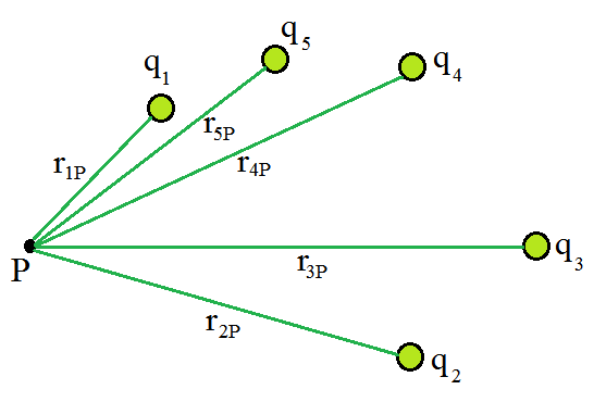
A single-point charge is rarely encountered in real life. Most of the systems found in real-life comprise multiple charges. For a system of point charges, the total potential at a point is given by the algebraic sum of the potential for individual charges at that point. The figure given below represents a system of point charges.
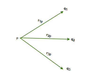
For example, in a system containing charges q1, q2, q3 at a distance of r1P, r2P, and r3P from a point. Then, the potential at this point by individual charges will be given by,
V1 = ,
V2 = ,
V3 =
The net potential due to these point charges is given by,
In general,
For a system of point charges containing charges q1, q2, q3,q4 …. at a distance of r1P, r2P and r3P…. from a point.
Solved Examples on Electric Potential
Example 1: Find the potential at a distance of 2 m from a point charge of 20pC.
Solution:
Potential due to a point charge is given by,
Here,
- q = 20 pC = 2 x 10-12 C
- r = 2 m
Plugging the values into this equation,
V =
⇒ V =
⇒ V = 9 × 109 × 1 × 10-11
⇒ V = 9 × 10⁻² V
Example 2: Find the potential at a distance of 5m from a point charge of 10pC.
Solution:
Potential due to a point charge is given by,
Here,
- q = 10 pC =10 × 10-12 C
- r = 5 m
Plugging the values into this equation,
V =
⇒ V =
⇒ V= 9 × 109 × 2 × 10-12
⇒ V= 18 x 10-3 V
Example 3: Find the potential at a distance of 1 m due to a charge of 10pC and -2pC.
Solution:
Potential due to a point charge is given by,
Here,
- q1 = 10 pC = 10 x 10-12 C
- q2 = -2 pC = -2 x 10-12 C
- r = 1 m
For two charges,
Plugging the values into this equation,
⇒ V= 36 × 10-3 V
Example 4: Find the potential at the center of a square of side a=2m due to a charge of 2pC and 2pC.
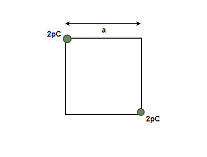
Solution:
Potential due to a point charge is given by,
Here,
- q1 = 2 pC = 2 x 10-12 C
- q2 = 2 pC = -2 x 10-12 C
Since the square is of side a = 2. The length of the diagonal will be 2√2.
This distance of the point from both the charges will be √2.
Thus,
- r = √2
For two charges,
Plugging the values into this equation,
Example 5: Find the potential at the origin due to the charges 1pC and -1pC located at (0,1) and (2,0).
Solution:
Potential due to a point charge is given by,
Here,
- q1 = 1 pC = 1 x 10-12 C
- q2 = 2 pC = -1 x 10-12 C
Distance of these charges from the center is,
- r1. = 1
- r2 = 2
Since there are two charges in the system, the total potential will be given by the superposition equation.
For two charges,
Plugging the values into this equation,
Example 6: Find the potential at the origin due to the charges 2pC and -10pC located at (0,3,4) and (0,0,5).
Solution:
Potential due to a point charge is given by,
Here,
- q1 = 1 pC = 1 x 10-12 C
- q2 = 2 pC = -1 x 10-12 C
Distance of these charges from the center is,
- r1 = √(02 + 32 + 42) = √(25) = 5
- r2 = 5
For two charges,
Plugging the values into this equation,
Check other Physics Links:
Electric Potential-FAQs
What is an Electric Charge?
Electric Charge is the property of the material that is used to define the electrostatic and electromagnetic properties of the material. There are two types of charges Positive Chagre and Negative Charge.
What is Electric Potential?
Electric potential is defined as the electric potential energy of a test charge placed at a point, divided by the magnitude of the charge. It is denoted by “V” and its formula is,
V = U / q
where,
- U is the Electric Potential Energy
- q is the charge
What is the SI unit of Electric Charge?
The SI unit of Electric Charge is “Columb” or “C”.
What is the SI unit of Electric Potential?
The SI unit of Electric Potential is “Volt” or “V”.
What is an Electric Dipole?
We define electric dipole by the two a set up that is formed by two charges separated by a distance “2d”. Then the electric dipole is the product of the charge and distance between them. It is denoted by “P”.
P = q.d
where,
- q is the charge
- d is the distance between them
Equipotential Surfaces
When an external force acts to do work, moving a body from a point to another against a force like spring force or gravitational force, that work gets collected or stores as the potential energy of the body. When the external force is excluded, the body moves, gaining the kinetic energy and losing an equal quantity of potential energy. The sum of kinetic and potential energies is hence conserved. Forces of this class are known as conservative forces. Examples of these forces are spring force and gravitational force.
Coulomb force is a conservative force between two (stationary) charges. Both have an inverse-square relationship on distance and differ only in the proportionality constants. The masses in the expression of gravitational law are replaced by charges in Coulomb’s law expression. Thus, like the potential energy of a mass in a gravitational field, the electrostatic potential energy of a charge in an electrostatic field is defined.
Equipotential Surface
A surface with a fixed potential value at all locations on the surface is known as an equipotential surface. For a single charge q, the potential can be expressed as

In the above expression, it is observed that if r is constant then V also remains constant. Therefore, equipotential surfaces of a single point charge are concentric spherical surfaces centered at the charge.
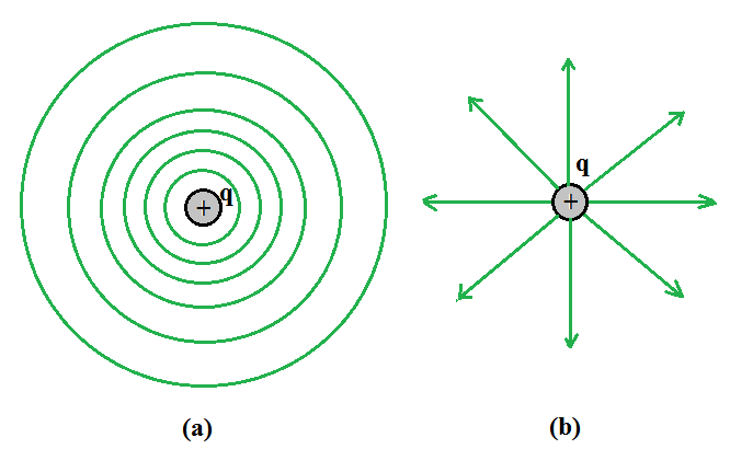
For a single charge q(a) equipotential surfaces are spherical surfaces centered at the charge, and(b) electric field lines are radial, starting from the charge if q > 0.
Depending on whether q is positive or negative, the electric field lines for a single charge q are radial lines that begin or finish at the charge. The electric field at each place is clearly normal to the equipotential surface that passes through that point. The equipotential surface through a point is normal to the electric field at that location for any charge arrangement. The proof for this assertion is straightforward.
The field has a non-zero component along the surface if it was not perpendicular to the equipotential surface. Work would be required to shift a unit test charge in the opposite direction as the component of the field. However, this contradicts the definition of an equipotential surface, which states that there is no potential difference between any two places on the surface and that no work is necessary to move a test charge over it. Therefore, at all points, the electric field must be normal to the equipotential surface. Equipotential surfaces allow an alternative visual image in addition to the image of electric field lines around a charge arrangement.
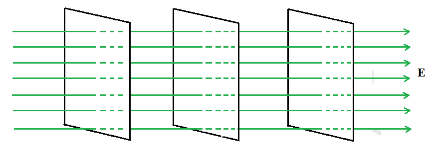
Equipotential surfaces for a uniform electric field.
For a uniform electric field E, say, along the x-axis, the equipotential surfaces are planes perpendicular to the x-axis, that is planes parallel to the y-z plane as shown in the above figure.
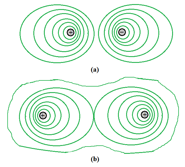
Some equipotential surfaces for (a) a dipole, (b) two identical positive charges.
The above figure is (a) Equipotential surfaces for a dipole and (b) Equipotential surfaces with two identical positive charges.
Work Done in Equipotential Surface
Moving a charge between two places on an equipotential surface is always zero. In an equipotential surface, if a point charge is transported from point A have potential energy VA to point B have potential energy VB, the work done to move the charge is given by
W = q(VA –VB) = 0
Because VA – VB = 0,
The total work done W is 0.
Properties of Equipotential Surface
- An equipotential surface has an electric field that is constantly perpendicular to it.
- It is impossible for two equipotential surfaces to intersect.
- Equipotential surfaces for a point charge are concentric spherical shells.
- For a uniform electric field, the equipotential surfaces are planes normal to the x-axis.
- The equipotential surface is directed from high potential to low potential.
- The potential inside a hollow charged spherical conductor is constant. Equipotential volume can be used to this. Moving a charge from the center to the surface requires no work done.
- The equipotential surface of an isolated point charge is a sphere. Different equipotential surfaces exist around the point charge, i.e. concentric spheres.
- Any plane normal to the uniform field direction is an equipotential surface.
- The distance between equipotential surfaces allows us to distinguish between strong and weak fields.
Electric Potential
The amount of work required to transport a unit charge from a reference point to a specific point against the electric field is known as electric potential.
When an object moves against an electric field, it gains energy that is referred to as electric potential energy. Divide the potential energy by the quantity of charge to get the charge’s electric potential. The electric field’s strength is determined by the electric potential. It is unrelated to whether or not a charge should be placed in the electric field. Electric potential is a scalar quantity. At point charge +q, all points with a distance of r have the same potential.
An object’s electric potential is determined by the following factors:
- An electric charge.
- The position of an electrically charged object in relation to other electrically charged objects.
Electric Potential Due to a Point Charge
Consider the origin of a point charge Q. Take Q to be positive. With position vector r from the origin, we want to find the potential at any point P. To do so, we must compute the amount of work required to transport a unit positive test charge from infinity to point P. When Q > 0, the work done on the test charge against the repulsive force is positive. We choose a handy path – along the radial direction from infinity to point P – since the work is done is independent of the path.
Work done in bringing a unit positive test charge from infinity to the point P, against the repulsive force of charge Q (Q > 0), is the potential at P due to the charge Q.
The electrostatic force on a unit positive charge at some intermediate point P′ on the path equals to
where ‘ } is the unit vector along OP′ therefore, work done against this force from r′ to r′ + ∆r′ can be written as
The negative sign represents ∆r′ < 0, ∆W is positive . Total work done (W) by the external force is determined by integrating the above equation both side, from r′ = ∞ to r′ = r,
The potential at P due to the charge Q can be expressed as
Sample Problems
Problem 1: Calculate the potential at a point P due to a charge of 4 × 10⁻⁷ C located 9 cm away.
Solution:
The potential at P due to the charge Q can be expressed as
Substituting the cave in the above expression,


Problem 2: Obtain the work done in bringing a charge of 2 × 10⁻⁹ C from infinity to point P. Does the answer depend on the path along which the charge is brought? (V= 4 × 10⁴ V)
Solution:
Given,
q= 2 × 10⁻⁹ C
V= 4 × 10⁴ V
The expression for work don is
W = qV
Substitute the value in the above expression,
W = 2 × 10–9 C × 4 × 104 V
W = 8 × 10⁻⁵ J
No, the work done will be path independent. Any infinitesimal path can be broken down into two perpendicular displacements: one along to r and one perpendicular to r. The work done relation to the latter will be zero.
Problem 3: Determine the electrostatic potential energy of a system consisting of two charges 7 µC and –2 µC (and with no external field) placed at (–9 cm, 0, 0) and (9 cm, 0, 0) respectively.
Solution:
Given,
Two charges 7 µC and –2 µC.
Distance between two points is 0.18 m.
The expression for the electrostatic potential energy is,
Substitute the value in the above expression,


Problem 4: 6 A molecule of a substance has a permanent electric dipole moment of magnitude 10–29 C m. A mole of this substance is polarized (at low temperature) by applying a strong electrostatic field of magnitude 106 V m–1. The direction of the field is suddenly changed by an angle of 60º. Estimate the heat released by the substance in aligning its dipoles along the new direction of the field. For simplicity, assume 100% polarization of the sample.
Solution:
Here, dipole moment of each molecule = 10–29 Cm.
As 1 mole of the substance contains 6 × 10²³ molecules.
Electrostatic field of magnitude 106 V m–1.
Total dipole moment of all the molecules can be written as
p = 6 × 1023 × 10–29 Cm
p = 6 × 10⁻⁶ Cm
Initial potential energy, Ui given by
Ui = –pE cos θ
Ui = –6×10–6×106 cos 0°
Ui = –6 J
Final potential energy (when θ = 60°), Uf
Uf = –6 × 10–6 × 106 cos 60°
Uf = –3 J
Change in potential energy = –3 J – (–6 J) = 3 J
So, there is loss in potential energy. This must be the energy released by the substance in the form of heat in aligning its dipoles.
Problem 5: Write the properties of Equipotential Surface.
Solution:
Following are the properties of equipotential surface.
- An equipotential surface has an electric field that is constantly perpendicular to it.
- It is impossible for two equipotential surfaces to intersect.
- Equipotential surfaces for a point charge are concentric spherical shells.
- For a uniform electric field, the equipotential surfaces are planes normal to the x-axis.
- The equipotential surface is directed from high potential to low potential.
- The potential inside a hollow charged spherical conductor is constant. Equipotential volume can be used to this. Moving a charge from the center to the surface requires no work done.
- The equipotential surface of an isolated point charge is a sphere. Different equipotential surfaces exist around the point charge, i.e. concentric spheres.
- Any plane normal to the uniform field direction is an equipotential surface.
- The distance between equipotential surfaces allows us to distinguish between strong and weak fields.
Potential Energy of a System of Charges
When an external force works to accomplish work, such as moving a body from one location to another against a force such as spring force or gravitational force, that work is collected and stored as the body’s potential energy. When the external force is removed, the body moves, acquiring kinetic energy and losing a corresponding amount of potential energy. As a result, the total kinetic and potential energy is preserved. Conservative forces are forces of this type. Spring force and gravitational force are two examples of these forces.
The Coulomb force is a conservative force that exists between two (stationary) charges. Both have an inverse-square relationship with respect to distance, with the only difference being the proportionality constants. The masses in the formulation of gravitational law are substituted by charges in the expression of Coulomb’s law. Thus, the electrostatic potential energy of a charge in an electrostatic field is defined in the same way as the gravitational potential energy of a mass in a gravitational field is.
What is an Electrostatic Potential?
The work done by an external force to carry a unit positive charge from infinity to a location is equal to the electrostatic potential (V) at that point is called the Electrostatic Potential.
Electric potential energy is a scalar quantity with no direction and only magnitude.
It is symbolized by V and has the dimensional formula [ML2T-3A-1].
Electric Potential Due to a Point Charge
Consider the origin of a point charge Q. Take Q to be positive. With position vector r from the origin, we want to find the potential at any point P. To do so, we must compute the amount of work required to transport a unit positive test charge from infinity to point P. When Q > 0, the work done on the test charge against the repulsive force is positive. We choose a handy path – along the radial direction from infinity to point P – since the work is done is independent of the path.
Work done in bringing a unit positive test charge from infinity to the point P, against the repulsive force of charge Q (Q > 0), is the potential at P due to the charge Q.
The electrostatic force on a unit positive charge at some intermediate point P′ on the path equals to
where is the unit vector along OP′ therefore, work done against this force from r′ to r′ + ∆r′ can be written as
The negative sign represents ∆r′ < 0, ∆W is positive . Total work done (W) by the external force is determined by integrating the above equation both side, from r′ = ∞ to r′ = r,
The potential at P due to the charge Q can be expressed as
Potential Energy of a System of Charges
Consider the simple situation of two charges, q1 and q2, with position vectors r1 and r2 relative to a point. Let’s calculate the work that went into putting this arrangement together (from the outside). This means that first start with the charges q1 and q2 at infinity and then figure out how much work done by an external agency to get the charges to the provided destinations. Assume that the charge q1 is first transferred from infinity to r1. Because there is no external field against which work must be performed, the amount of work required to bring q1 from infinity to r1 is zero. This charge produces a potential in space that can be written as,
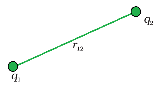
3 Potential energy of a system of charges q1 and q2 is directly proportional to the product charges and inversely to the distance between them.
where r1P is the distance of a point P in space from the location of q1. From the definition of potential, work done in bringing charge q2 from infinity to the point r2 is q2 times the potential at r2 due to q1,

where r12 is the distance between points 1 and 2. Since electrostatic force is conservative, this work gets collected in the form of the potential energy of the system. Thus, the potential energy of a system of two charges q1 and q2 can be written as,
 ……..(1)
Clearly, the potential energy U would be the same if q2 was transferred first to its current location and q1 was brought later.
Potential energy is positive if q1 q2 > 0. This is to be expected, because the electrostatic force is repulsive for like charges (q1 q2 > 0), and a positive amount of effort must be done against it to get the charges from infinity to a finite distance apart. The electrostatic force is attractive for dissimilar charges (q1q2< 0). To take the charges from the specified point to infinity, a positive quantity of work against this force is required. In other words, the reverse path (from infinity to the present places) requires a negative amount of work, hence the potential energy is negative.
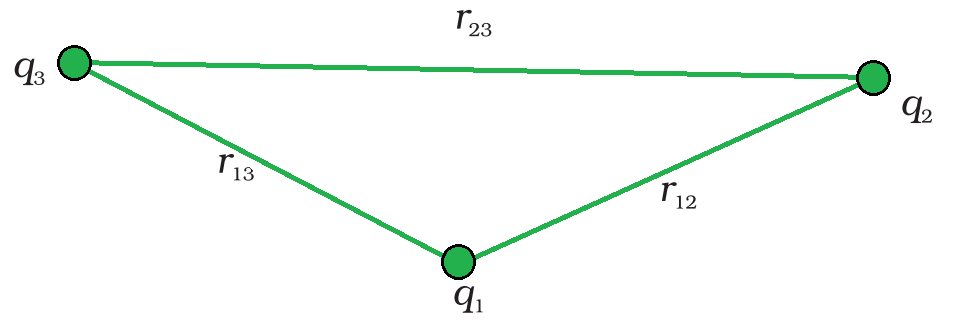
The potential energy of a system of three charges.
Equation (1) can be easily generalized to any number of point charges in a system. Calculate the potential energy of a system with three charges q1, q2, and q3 at distances r1, r2, and r3 respectively. There is no work required to bring q1 first from infinite to r1. Bring next, bring q2 to r2 from infinity. As previously stated, the work completed in this step is
 ……(2)
……(2)
The charges q1 and q2 generate a potential, which at any point P can be written as

Work done next in bringing q3 from infinity to the point r3 is q3 times V1,2 at r3 can be written as,
 …….(3)
The total work done in collecting the charges at the given locations is obtained by adding equations (2) and (3),

The final formula for U is independent of the method in which the configuration is formed due to the conservative nature of the electrostatic force (or, equivalently, the path independence of work done). The potential energy is a property of the current state of configuration, not the method by which it was produced.
Potential due to a System of Charges
Potential at a point due to a system of charges is the sum of potentials due to individual charges.
Suppose a system of charges q1, q2,…, qn with position vectors r1, r2,…, rn relative to some origin. The potential V1 at P due to the charge q1 is
where r1P is the distance between q1 and P.
Similarly, the potential V2 at P due to q2 and V3 due to q3 can be written as,
where r2P and r3P are the distances of P from charges q2 and q3 , respectively; and so on for the potential due to other charges. By the superposition principle, the potential V at P due to the total charge configuration is the algebraic sum of the potentials due to the individual charge that is,
V = V1 + V2 + V3 +…… + Vn
The above expression can be expressed as,

A continuous charge distribution with a charge density ρ (r), must be divided into small volume elements of size ∆v, each carrying a charge ρ ∆v. Then calculate the potential due to each volume element and add (or, more precisely, integrate) all of these contributions to get the total potential due to the distribution.
Sample Problems
Problem 1: Two charges 3 × 10⁻⁸ C and –2 × 10⁻⁸ C are located 15 cm apart. At what point on the line joining the two charges is the electric potential zero? Take the potential at infinity to be zero.
Solution:
Let us take the origin O at the location of the positive charge. The line joining the two charges is taken to be the x-axis; the negative charge is taken to be on the right side of the origin.
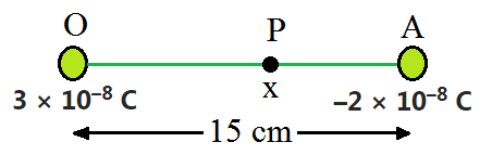
Let P be the expected point on the x-axis where the potential is zero. If x is the x-coordinate of P, and therefore x must be positive. If x lies between O and A, then
Rearrange the above equation to find the value of x,
which gives x = 9 cm.
If x lies on the extended line OA, the required condition is
which results x = 45 cm.
On the side of the negative charge, an electric potential is zero at 9 cm and 45 cm away from the positive charge.
![\frac{1}{4\pi\epsilon_0}\left[\frac{3\times10^{-8}}{x\times10^{-2}}-\frac{2\times10^{-8}}{(15-x)\times10^{-2}}\right]=0](https://www.geeksforgeeks.org/wp-content/ql-cache/quicklatex.com-f3d6efb38825d094e0ce8c0299faaff3_l3.svg "Rendered by QuickLaTeX.com")


Problem 2: Figures (a) and (b) show the field lines of a positive and negative point charge respectively.
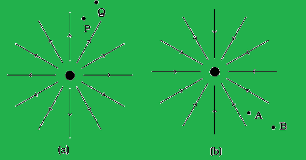
(a) Give the signs of the potential difference VP – VQ; VB – VA.
(b) Give the sign of the potential energy difference of a small negative charge between the points Q and P; A and B.
(c) Give the sign of the work done by the field in moving a small positive charge from Q to P.
(d) Give the sign of the work done by the external agency in moving a small negative charge from B to A.
(e) Does the kinetic energy of a small negative charge increase or decrease in going from B to A?
Solution:
(a) As V ∝ (1/r) and VP> VQ. Thus, (VP – VQ) is positive. Also, VB is less negative than VA. Thus, VB > VA or (VB – VA) is positive.
(b) A tiny negative charge will be attracted towards a positive charge. The negative charge moves from higher potential energy to lower potential energy. Therefore, the sign of potential energy difference of a small negative charge between Q and P is positive. Similarly, VA > VB and hence the sign of potential energy differences are positive.
(c) In moving a small positive charge from Q to P, work has to be done by an external agency against the electric field. Therefore, work done by the field is negative.
(d) In moving a small negative charge from B to A work has to be done by the external agency. It is positive.
(e) Due to the force of repulsion on the negative charge, velocity decreases and hence the kinetic energy decreases in going from B to A.
Problem 3: A 500 µC charge is at the center of a square of side 10 cm. Find the work done in moving a charge of 10 µC between two diagonally opposite points on the square.
Solution:
Because these two locations are at equipotential, the work done in transporting a charge of 10 C between two diagonally opposite spots on the square will be zero.
Problem 4: (a) Can two equipotential surfaces intersect each other? Give reasons.
(b) Two charges -q and + q are located at points A (0, 0, – a) and B (0, 0, +a) respectively. How much work is done in moving a test charge from point P (7, 0, 0) to Q (-3,0,0)?
Solution:
(a) No, if they intersect, the electric field will be in two distinct directions, which is incorrect. If they cross, there will be two potential values at the same point of intersection. Because this isn’t conceivable, two equipotential surfaces can’t meet.
(b) Work done will be zero since both points P and Q are on the dipole’s equatorial line, which has V = 0 at all points. Furthermore, because any charge’s force is perpendicular to the equatorial line, no work is done.
Problem 5: “For any charge configuration, equipotential surface through a point is normal to the electric field.” Justify.
Solution:
Work done in moving a charge over an equipotential surface is zero, hence a point on it will be normal to the electric field.
W = Fs cos θ
∴ cos θ = 0
or
θ = 90o
Problem 6: Why must the electrostatic potential inside a hollow charged conductor be the same at every point?
Solution:
Because the electric field inside the hollow charged conductor is zero, no work is done in moving a small test charge within the conductor. As a result, the electrostatic potential inside a hollow charged conductor remains constant.
Potential Energy in an External Field
When an external force operates to conduct work, such as moving a body from one location to another against a force like spring force or gravitational force, the work is gathered and stored as potential energy in the body. When an external force is removed, the body moves, acquiring kinetic energy and losing potential energy in equal amounts. As a result, the total kinetic and potential energy are conserved. Conservative forces are those who belong to this group. Spring force and gravitational force are two examples of these forces.
Table of Content
What is Potential Energy?
Potential energy is a type of stored energy found in an object, which is not currently in motion but has the potential to become active.
Potential Energy in an External Field
Coulomb force is a conservative force between two (stationary) charges. Both have an inverse-square relationship on distance and differ only in the proportionality constants. The masses in the expression of gravitational law are replaced by charges in Coulomb’s law expression. Thus, like the potential energy of a mass in a gravitational field, the electrostatic potential energy of a charge in an electrostatic field is defined.
Potential Energy of a Single Charge
The charges and their locations were previously given as the source of the electric field, and the potential energy of the system of those charges was calculated. The most significant distinction is that now our concerned with the potential energy of a charge (or charges) in an external field. The specified charge(s) whose potential energy want to calculate does not produce the external field E. E is generated by sources outside the provided charge (s). External sources may be identified, however, they are frequently unknown or unspecified.
Assume that the charge q does not affect the sources that generate the external field. This is true if q is very tiny, or if unspecified forces hold the external sources in place. Even if q is limited, its impact on external sources may be overlooked in the case of extremely powerful sources far away at infinity producing a finite field E in the region of interest.
From point to point, the external electric field E and the related external potential V may differ. V at point P is defined as the work required to deliver a unit positive charge from infinity to point P. As a result, the amount of work required to transport a charge q from infinity to point P in the external field is qV.
This work is stored in the form of the potential energy of q. If the point P has position vector r relative to some origin can be written as,
Potential Energy of q at r in an external field = qV(r)
where,
- V(r) is the external potential at point r
Thus, if an electron with charge q = e = 1.6×10⁻¹⁹ C is accelerated by a potential difference of ∆V = 1 volt, it would gain energy of q∆V = 1.6 × 10⁻¹⁹ J.
This unit of energy is defined as 1 electron volt or 1eV,
i.e. 1 eV=1.6 × 10⁻¹⁹ J.
Electric Potential Due to a Point Charge
The electrostatic potential represents the energy needed to bring a positive unit charge from infinity to a specific location, exerted by an external force. Now, we’ll derive the formula for the electric potential resulting from a point charge.
Consider a charge (Q) placed in an electric field, where the magnitude of the field is (E), and (q) represents a very small charge. The potential energy of (Q) within this electric field equals the work required to move that charge from infinity.
The electrostatic force acting on a single positive charge (Q) at a point (p) is given by:
F = Q q/ 4π𝜀or2
Therefore, the work done is:
W = Q / 4π𝜀or
The potential at point (P) due to the charge (Q) is expressed as:
V(r) = Q / 4π𝜀or
Potential Energy of a System of Two Charges in an External Field
Potential energy of a system of two charges q1 and q2 located at r1 and r2, respectively, in an external field. To begin, compute the amount of work required to get the charge q1 from infinite to r1. q1 V(r1) is the work done in this step. After that, the work that went into getting q2 to r2. Work is done against the external field E and the field created by q1 in this phase.
Work done on q2 against the external field = q2V(r2 )…(1)
Work done on q2 against the field due to q1 is equal to (q1q2/4πεor12 )…(2)
where r12 is the distance between q1 and q2. By the superposition principle for fields, add up (equation (1) and equation (2))the work done on q2 against the two fields (E and that due to q1 ).
Work done in bringing q2 to r2 is equal to q2V(r2 ) + (q1q2/4πεor12 )
Thus, Potential energy of the system = the total work done in assembling the configuration
= q1V(r1 ) + q2V(r2 ) + (q1q2/4πεor12)…(3)
Potential Energy of a Dipole in an External Field
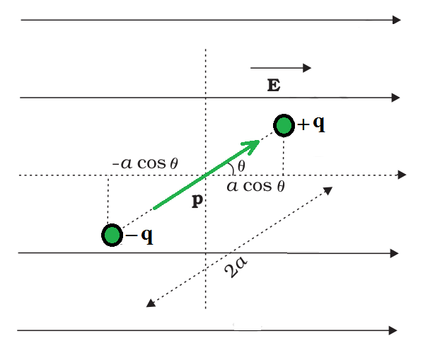
Potential Energy of a Dipole in an External Field
Suppose a dipole with charges q1 = +q and q2 = –q is placed in a uniform electric field E. The dipole feels no net force in a homogeneous electric field but does experience a torque defined as,
τ = p × E
which will tend to rotate it.
Assume that an external torque τext is applied in such a way that it simply neutralizes the torque and rotates it in the plane of paper at an infinitesimal angular speed and without angular acceleration from angle θ0 to angle θ1. The amount of work done by the external torque can be written as,
This work is saved as the system’s potential energy. The potential energy U(θ) can then be linked to the dipole’s inclination θ. There is a degree of freedom in choosing the angle at which the potential energy U is regarded to be zero, just as there is with other potential energies. Taking θ0 = π/ 2 is a natural decision.
This expression can alternately be understood also from Equation (3). apply Equation (3) to the present system of two charges +q and –q.
……(4)
The location vectors of +q and –q is denoted by r1 and r2. The work done in transporting a unit positive charge against the field from r2 to r1 is now equal to the potential difference between positions r1 and r2. 2a×cosθ is the displacement parallel to the force.
Therefore, [V(r1) – V(r2)] = -E×2a×cosθ
So, equation (4) can be written as,
Note, U′(θ) differs from U(θ) by a quantity which is just a constant for a given dipole.
Electrostatic Potential
Consider any static charge setup in general. The potential energy of a test charge q is defined in terms of the work done on it. Because the force at any place is qE, where E is the electric field at that point due to the given charge arrangement, this work is obviously proportional to q. As a result, it is convenient to divide the work by the amount of charge q, resulting in a quantity that is independent of q. In other words, work done per unit test charge is representative of the electric field linked with the charge configuration. This reaches the idea of electrostatic potential V due to a given charge configuration. The Work done by external force in carrying a unit positive charge from point R to P can be expressed as,
where, VP and VR are the electrostatic potentials at P and R, respectively.
“Work done by an external force to carry a unit positive charge from infinity to a location is equal to the electrostatic potential (V) at that point.”
In other words, the electrostatic potential (V ) at any location in an area with an electrostatic field is the work required to transport a unit positive charge from infinity to that location (without acceleration). Electric potential energy is a scalar quantity with no direction and only magnitude. It is symbolized by V and has the dimensional formula ML2T-3A-1.
Sample Problems
Problem 1: Derive an expression for the total work done in rotating an electric dipole through an angle θ in a uniform electric field?
Solution:
Expression for the torque can be written as,
T = PE sinθ
If an electric dipole is rotated through an angled against the torque acting on it, then small amount of work done is
dw =Tdθ = PE sinθ dθ
For rotating through on angle θ, from 90o
Problem 2: A system consisting of two charges 8 µC and –6 µC (and with no external field) placed at (–9 cm, 0, 0) and (9 cm, 0, 0) respectively. Determine how much work is required to separate the two charges infinitely away from each other?
Solution:
To determine the work required to separate the two charges infinitely away from each other, we need to calculate the change in potential energy of the system as the charges are moved from their initial positions to infinity.
potential energy (U) of a system of charges-
U = (1/4πε0)/[(q1q2)/r]
q1 = 8 µC = 8 × 10⁻⁶ C
q1 = -6 µC = -6 × 10⁻⁶ C
distance (r) = 18 cm = 0.18 m
let’s calculate potential energy (U)
U = (1/4πε0)/[(q1q2)/r]
U = 1/(4π × 8.85 × 10-12) × {[(8×10⁻⁶) (-6×10⁻⁶)] / 0.18}
U = (-48 x 10-12 ) /0.18
U = -2.667 x 10⁻⁷ J
Work required to separate the two charges infinitely away from each other is the difference in potential energy:
W = Ufinal – Uinitial = 0 – (-2.667 x 10⁻⁷) = 2.667 x 10 -7 J
Work required to separate the two charges infinitely away from each other = 2.667 x 10⁻⁷ J
Problem 3: Two charged conducting spheres of radii a and b are connected to each other by a wire. What is the ratio of electric fields at the surfaces of the two spheres? Use the result obtained to explain why charge density on the sharp and pointed ends of a conductor is higher than on its flatter portions.
Solution:
Let a be the radius of a sphere A, QA be the charge on the sphere, and CA be the capacitance of the sphere. Let b be the radius of a sphere B, QB be the charge on the sphere, and CB be the capacitance of the sphere. Since the two spheres are connected with a wire, their potential (V) will become equal.
Let EAbe the electric field of sphere A and EB be the electric field of sphere B. Therefore, their ratio,
Since, \frac{Q_A}{Q_B}=\frac{C_AV}{C_BV} and
There fore the equation (1) can be expressed as,
Problem 4: What is the area of the plates of a 2 F parallel plate capacitor, given that the separation between the plates is 0.5 cm? [You will realize from your answer why ordinary capacitors are in the range of µF or less. However, electrolytic capacitors do have a much larger capacitance (0.1 F) because of very minute separation between the conductors.]
Solution:
Given,
- Capacitance of a parallel capacitor, V = 2 F
- Distance between the two plates, d = 0.5 cm = 0.5×10⁻² m
Capacitance of a parallel plate capacitor is given by the relation,
C = εoA/d
where,
εo = Permittivity of free space = 8.85×10⁻¹² C2N-1m-2
A = (2×0.5×10-2)/8.85×10-12
A = 1130 km2
Hence, area of plates is too large. To avoid this situation, the capacitance is taken in the range of µF.
Problem 5: What is the work done in moving a test charge q through a distance of 1 cm along the equatorial axis of an electric dipole?
Solution:
Since potential for equatorial axis is zero, i.e.
V = 0
Therefore,
W = qV = 0
Problem 6: Define the term ‘potential energy of charge ‘q’ at a distance V in an external electric field.
Solution:
It is defined as the amount of work done in bringing the charge from infinity to its position in the system in the electric field of another charge without acceleration.
V = Er
Problem 7: A hollow metal sphere of radius 5 cm is charged such that the potential on its surface is 10 V. What is the potential at the center of the sphere?
Solution:
Electric field inside the shell is zero. This implies that potential is constant inside the shell (as no work is done in moving a charge inside the shell) and, therefore, equals its value at the surface, which is 10 V.
Electrostatics of Conductors
When an external force is used to remove a body from a situation. Point to another in the face of a force like spring or gravitational force That work is stored in the body as potential energy. When the external environment When a force is eliminated, the body moves, gaining and losing kinetic energy. An amount of potential energy that is equal. The total amount of kinetic and As a result, potential energy is conserved. This type of force is referred to as Conservative forces are at work. Examples of forces include spring force and gravitational force. Conservative forces are at work.
What are Conductors?
A metal rod rubbed with wool in the hand will not exhibit any evidence of being charged. A metal rod with a wooden or plastic grip, on the other hand, exhibits symptoms of charge when brushed with wool without touching its metal part. Consider a copper wire with one end linked to a neutral pith ball and the other to a negatively charged plastic rod. The pith ball acquires a negative charge, as can be seen. A similar experiment using a nylon thread or a rubber band yielded no charge transfer from the plastic rod to the pith ball.
Conductors are materials that permit the free flow of electricity through them. Inside the material, they have comparatively free-moving electric charges (electrons). Metals, human and animal bodies, and the ground itself are all conductors.
As a safety measure, earthing electrical circuits and equipment are beneficial. A large metal plate is buried deep in the ground, and thick wires are dragged from it to connect houses to the earth near the mains supply. The electrical wiring in our homes is made up of three wires: live, neutral, and earth. The first two transport power from the power plant, while the third is earthed by connecting to a buried metal plate. Electric equipment such as electric irons, refrigerators, and televisions have an earth wire that is attached to the metallic body. When a fault happens or a live wire comes into contact with the metallic body, the charge flows to the earth without destroying the appliance or injuring humans; otherwise, because the human body is a conductor of electricity, this would have been unavoidable.
Electrostatics of Conductors
Mobile charge carriers are found in conductors. Electrons are the charge carriers in metallic conductors. The outside (valence) electrons of metal separate from their atoms and become free to move. These electrons are free to move about within the metal but not outside it. The liberated electrons form a kind of ‘gas,’ colliding with one other and the ions as they move in random directions. They float in the opposite direction of an external electric field. The positive ions, which are made up of nuclei and bound electrons, are maintained in place. The charge carriers in electrolytic conductors are both positive and negative ions; however, the situation is more complicated in this case since the charge carriers’ movement is influenced by both the external electric field and the so-called chemical forces. Let’s take a look at some key findings in conductor electrostatics.
- Inside a conductor, an electrostatic field is zero.
Consider a neutral or charged conductor. There could also be an electrostatic field outside the room. The electric field is zero everywhere inside the conductor in a static scenario, when there is no current inside or on the surface of the conductor. This fact can be considered a conductor’s defining characteristic. Free electrons exist in a conductor. The free charge carriers will suffer force and drift as long as the electric field is not zero. The free charges have dispersed themselves so evenly inside the static condition that the electric field is zero everywhere. Inside a conductor, the electrostatic field is zero.
- At the surface of a charged conductor, the electrostatic field must be normal to the surface at every point.
E would have a non-zero component along the surface if it wasn’t normal to the surface. The free charges on the conductor’s surface would then be forced to shift. As a result, in a static scenario, E should have no tangential component. As a result, the electrostatic field at the surface of a charged conductor must be perpendicular to the surface at all times. (Field is zero even at the surface of a conductor with no surface charge density.)
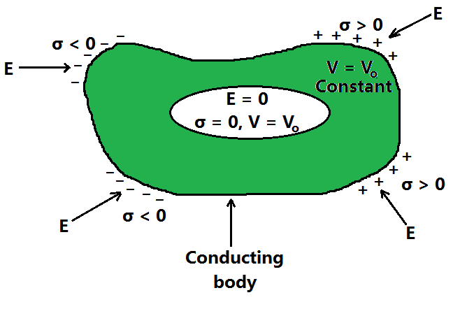
- The interior of a conductor can have no excess charge in a static situation.
Every little volume or surface element in a neutral conductor has the same quantity of positive and negative charges. When the conductor is charged in a static condition, the excess charge can only dwell on the surface. This is based on Gauss’s law. Consider a conductor with any arbitrary volume element v. The electrostatic field is zero on the closed surface S that surrounds the volume element v. As a result, the total electric flux passing through S is zero. As a result, according to Gauss’ law, there is no net charge enclosed by S. However, the surface S can be made as small as desired, resulting in a vanishingly small volume v. This means that there is no net charge inside the conductor at any point, and any excess charge must be discharged at the surface.
- The electrostatic potential is constant throughout the volume of the conductor and has the same value (as inside) on its surface.
This follows the point 1 and 2 which is mention above. There is no work done in moving a small test charge within the conductor and on its surface because E = 0 inside the conductor and has no tangential component on the surface. That is, no potential difference exists between any two places inside or on the conductor’s surface. As a result, the outcome. If the conductor is charged, an electric field normal to the surface exists; this means the surface and a point just outside the surface have different potentials. Each conductor in a system of conductors of arbitrary size, shape, and charge arrangement is defined by a constant value of potential, which may differ from one conductor to the next.
- The electric field at the surface of a charged conductor
 …………….(1)
where σ is the surface charge density and  is a unit vector normal to the surface in the outward direction.
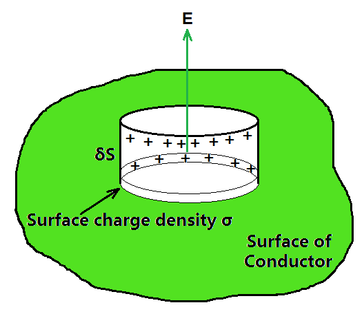
The Gaussian surface (a pillbox) was chosen to derive the electric field at the surface of a charged conductor.
To get the result, choose a pillbox (a short cylinder) as the Gaussian surface around any point P on the surface, as shown in the above figure. The pillbox is partially inside and partially outside the conductor’s surface. It has a tiny cross-sectional area δS and a low height. The electrostatic field is zero just inside the surface, and it is normal to the surface with magnitude E just outside. As a result, only the pillbox’s outside (circular) cross-section contributes to the total flux through the pillbox. This equals ES (positive for σ > 0, negative for σ < 0), because E is constant over the tiny area S, and E and S are parallel or antiparallel. σ δS is the charge carried by the pillbox.
According to Gauss’s law,

The fact that the electric field is perpendicular to the surface, the vector relation, equation (1) is true for both signs of σ. For σ > 0, the electric field is normal to the surface outward; for σ < 0, the electric field is normal to the surface inward.
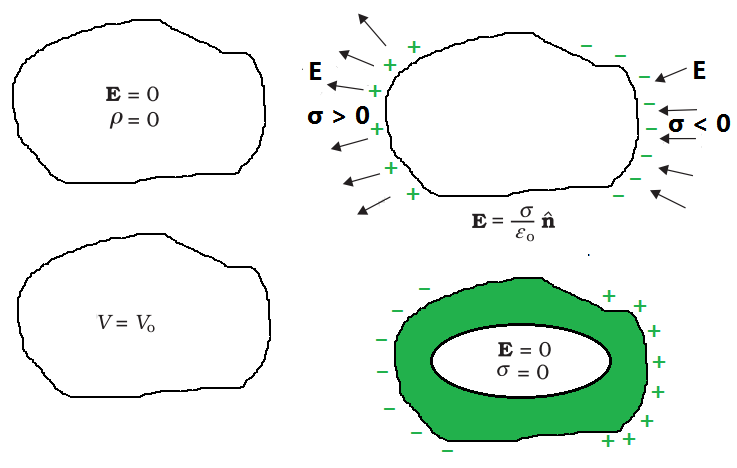
- Electrostatic shielding
Consider a conductor with a hollow that contains no charges. The electric field inside the cavity is zero, regardless of the size and shape of the cavity and the charge on the conductor, and the external fields in which it may be positioned. This result has already been shown in a basic case: the electric field inside a charged spherical shell is zero. The spherical symmetry of the shell is used in the proof of the result for the shell. However, as previously stated, the disappearance of the electric field in the (charge-free) cavity of a conductor is a very general result. A related result is that all charges remain only on the outer surface of a conductor with a cavity, even if the conductor is charged or charges are induced on a neutral conductor by an external field.
8The electric field inside the cavity of any conductor is zero. All charges reside only on the outer surface of a conductor with a cavity. (There are no charges placed in the cavity.)
The proofs of the above-mentioned results are omitted in the above figure, but their significance is highlighted. Any cavity in a conductor is protected from outside electric effect, regardless of the charge and field configuration outside: the field inside the cavity is always zero.
Some important electrostatic properties of a conductor
Electrostatic shielding is the term for this. The effect can be used to shield delicate devices from electrical interference from the outside world. The electrostatic properties of a conductor are summarized in the above figure.
Sample Problems
Problem 1: (a) A comb run through one’s dry hair attracts small bits of paper. Why? What happens if the hair is wet or if it is a rainy day? (Remember, the paper does not conduct electricity.)
(b) Ordinary rubber is an insulator. But special rubber tyres of aircraft are made slightly conducting. Why is this necessary?
(c) Vehicles carrying inflammable materials usually have metallic ropes touching the ground during motion. Why?
(d) A bird perches on a bare high power line, and nothing happens to the bird. A man standing on the ground touches the same line and gets a fatal shock. Why?
Solution:
(a) This is because the comb gets charged by friction. The molecules in the paper gets polarised by the charged comb, resulting in a net force of attraction. If the hair is wet, or if it is a rainy day, friction between hair and the comb reduces. The comb does not get charged, and thus it will not attract small bits of paper.
(b) To enable them to conduct charge (produced by friction) to the ground; as too much of static electricity accumulated may result in spark and result in fire.
(c) To enable them to conduct charge (produced by friction) to the ground; as too much of static electricity accumulated may result in spark and result in fire.
(d) Current passes only when there is a difference in potential.
Problem 2: A slab of material of dielectric constant K has the same area as the plates of a parallel-plate capacitor but has a thickness (3/4)d, where d is the separation of the plates. How is the capacitance changed when the slab is inserted between the plates?
Solution:
Let E0 = V0 /d be the electric field between the plates when there is no dielectric and the potential difference is V0 . If the dielectric is now inserted, the electric field in the dielectric will be E = E0 /K. The potential difference will then be
The potential difference decreases by the factor (K + 3)/K while the free charge Q0 on the plates remains unchanged. The capacitance thus increases


Problem 3: A 500 µC charge is at the Centre of a square of side 10 cm. Find the work done in moving a charge of 10 µC between two diagonally opposite points on the square.
Solution:
The work done in moving a charge of 10 µC between two diagonally opposite points on the square will be zero because these two points will be at equipotential.
Problem 4: Why must the electrostatic potential inside a hollow charged conductor be the same at every point?
Solution:
Because the electric field inside the hollow charged conductor is zero, no work is done in moving a small test charge within the conductor. As a result, the electrostatic potential inside a hollow charged conductor remains constant.
Problem 5:
(i) Can two equipotential surfaces intersect each other? Give reasons.
(ii) Two charges -q and + q are located at points A (0, 0, – a) and B (0, 0, +a) respectively. How much work is done in moving a test charge from point P (7, 0, 0) to Q (-3,0,0)?
Solution:
(i) No, if they intersect, the electric field will be in two distinct directions, which is incorrect. If they cross, there will be two potential values at the same place of intersection. Because this isn’t conceivable, two equipotential surfaces can’t meet.
(ii) Work done will be zero since both points P and Q are on the dipole’s equatorial line, which has V = 0 at all points. Furthermore, because any charge’s force is perpendicular to the equatorial line, no work is done.
Dielectrics and Polarisation
Have you noticed how many of the insulators are made of wood, plastic, or glass? But why is that? When we utilise wood or plastic, why don’t we receive electric shocks? Why do you only get severe shocks from metal wires? We’ll look at dielectrics, polarisation, the dielectric constant, and more in this chapter. We’ll look at some typical applications and examples of these dielectrics as well.
Table of Content
What is a Dielectric?
Non-conducting materials are known as dielectrics. They are insulating materials and poor electric current conductors. Dielectric materials can maintain an electrostatic charge while losing very little energy as heat. Mica, plastics, glass, porcelain, and other metal oxides are examples of dielectrics. It’s also important to note that even dry air is dielectric.
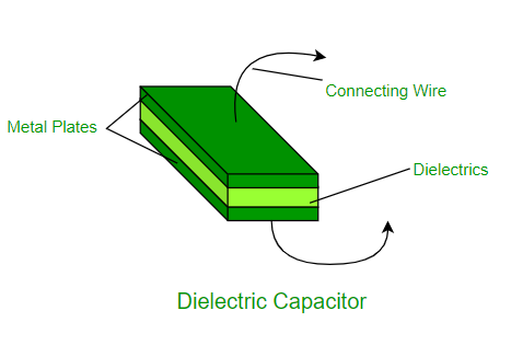
Classification of Dielectrics
Dielectrics are of two types:
- Polar Molecules: Polar Molecules are those types of dielectrics in which the chances of positive and negative molecules colliding are nil or zero. This is because they are all asymmetrical in form. H2O, CO2, NO2, and other gases are examples. When there is no electric field, the electric dipole moment of these molecules moves in an unpredictable direction. The average dipole moment is 0 as a result of this. If there is an external electric field, the molecules will assemble in the same direction as the electric field.
- Non-Polar Molecule: Unlike polar molecules, the centre of positive and negative charge in non-polar molecules does not coincide, i.e., zero. There is no longer any persistent (or inherent) dipole moment in the molecule. Examples include O2, N2, H2, and others.
Induced Electric Dipole Moment
When an external electric field is applied to a non-polar molecule, all protons move in the same direction as the electric field, while electrons move in the opposite direction. This process will continue unless the internal pressures are balanced due to the existence of an electric field. This results in the formation of two charge centres. We name them the Induced Electric Dipole because they are polarised. The Induced Electric Dipole Moment is the dipole moment.
Polarizability
When the matter is exposed to an electric field, it has a propensity to develop an electric dipole moment that is proportional to the applied field. Because matter is made up of fundamental particles with an electric charge, such as protons and electrons, it is a property of all matter.
Negatively charged electrons and positively charged atomic nuclei are subjected to opposing forces and undergo charge separation when exposed to an electric field. The dielectric constant and, at high (optical) frequencies, the refractive index of a material is determined by its polarizability.
The applied field is proportional to the induced dipole moment and is temperature independent. For a single polar atom, the direction of induced dipole moment (x) is parallel to the direction of electric field E. The polarisability of a bound system influences its dynamical responsiveness to external fields.
It also gives information about a molecule’s interior structure. Polarizability is a solid is defined as the dipole moment per unit volume of the crystal cell:
P = ε0 α E
where α is the atomic polarizability & E is the electric field.
Its S.I. unit is m3 and its dimensions are the same as its volume.
Electric Polarization
When the matter is exposed to an electric field, it has a propensity to develop an electric dipole moment that is proportional to the applied field. Because matter is made up of fundamental particles with an electric charge, such as protons and electrons, it is a property of all matter.
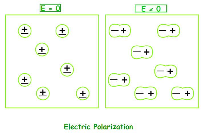
Dielectric Constant
The Dielectric Constant is the ratio of the applied electric field strength to the strength of the decreased value of the electric field capacitor when a dielectric slab is placed between the parallel plates. The formula is as follows:
εr = E0 / E
where E0 is the applied electric field, E is the net field, & εr is the dielectric constant.
The greater the dielectric constant, the greater the amount of charge that can be held. The capacitance of a capacitor is increased by a factor of the dielectric constant when the gap between the plates is completely filled with a dielectric. C = εr C0, where C0 is the capacitance between the plates with no dielectric.
Dielectric Strength
The dielectric strength of insulating material is the highest electric field strength that it can tolerate intrinsically without losing its insulating characteristics.
Dielectric Polarization
Dielectric Polarization occurs when an external electric field is applied to a dielectric substance. When an electric field is applied, it causes charges (both positive and negative) to be displaced. The primary goal of dielectric polarisation is to connect macroscopic and microscopic characteristics.
In the case of piezoelectric crystals, polarization is caused by the action of an electric field or other external variables such as mechanical stress. Solid materials that collect electric charge are known as piezoelectric crystals.
Dielectric In pyroelectric crystals, polarization can also occur spontaneously, especially in ferroelectrics. Ferroelectricity is a feature of some materials in which the electric polarisation may be reversed by applying an electric field.
The formula for polarization is given as:
P = ε0 χe E = ε0 (εr − 1) E
where P is the polarization, χe is the susceptibility, & E is the electric field.
Properties of Dielectric Polarisation
Alignment of Electric Dipoles: Dielectric polarization involves the alignment of electric dipoles within the material in response to an external electric field. These dipoles can be induced, permanent, or a combination of both.
Opposing Electric Field: The alignment of dipoles creates an internal electric field that opposes the external electric field. This opposing field weakens the overall electric field within the dielectric material.
Dielectric Constant: The dielectric constant (also known as relative permittivity) of a material quantifies its ability to polarize in response to an electric field. It is the ratio of the electric displacement field to the electric field applied to the material.
Types of Polarization: There are different mechanisms through which polarization can occur in dielectric materials, including electronic polarization, ionic polarization, and orientation polarization.
Electronic Polarization: In electronic polarization, the displacement of electrons within atoms or molecules contributes to the polarization of the material. This occurs primarily in covalently bonded materials.
Sample Questions
Question 1: Electric field inside the capacitor is 50 V/m and the dielectric constant = 4.5. What is polarization?
Answer:
Given:
Dielectric Constant, εr = 4.5
Electric Field, E = 50 V/m
Susceptibilty, χe = εr − 1 = 4.5 − 1 = 3.5
Polarization, P = χe E
= 3.5 × 50
= 175 C/m2
Hence, the polarization is 175 C/m2.
Question 2: What is dielectric polarization?
Answer:
When an external electric field is applied to a material, dielectric polarisation is the term used to describe its behaviour. An externally applied electric field causes a dipole moment to develop in an insulating material, which is known as dielectric polarisation.
When a current interacts with a dielectric (insulating) substance, the dielectric material shifts its charge distribution, with positive charges aligning with the electric field and negative charges aligning with the electric field. Important circuit components like capacitors may be manufactured by taking use of this reaction.
Question 3: The relative dielectric constant of polystyrene is 3.5. What is the polarization produced when a 1.5 mm thick sheet of polystyrene is subjected to 240 V?
Answer:
Given that,
Dielectric constant,
εr = 3.5
ε0 = 8.85 × 10⁻¹² C / V m
Thickness, d = 1.5 mm = 1.5 × 10⁻³ m
Voltage, V = 240 V
Electric Field, E = V/d
= 240 / (1.5 × 10⁻³) V/m
= 1.6 × 10⁵ V/m
Polarization, P = ε0 (εr − 1) E
= 8.85 × 10−12 × (3.5 – 1) × 1.5 × 105 C/m2
= 3.32 × 10⁻⁶ C/m2
Hence, the polarization produced in polystyrene is 3.32 × 10⁻⁶ C/m2.
Question 4: Explain insulators and their properties?
Answer:
Insulators are materials that make it difficult for electric charges to flow freely. The outer shell electrons are firmly linked to the nucleus in the atoms of such substances. These chemicals have a high impedance to the passage of electricity because they lack free charge carriers. Glass, diamond, porcelain, plastic, nylon, wood, mica, and other non-metals are all insulators.
Properties:
- Insulators have a poor conductivity and a high resistance.
- Their atoms contain electrons that are firmly bonded and do not migrate throughout the substance.
- A current cannot readily flow because the electrons are stagnant and not freely moving.
Question 5: What are dielectric materials?
Answer:
Dielectric materials are insulating materials that are poor conductors of electric current. When a dielectric is put in an electric field, it shows an electric dipole, which means that positive and negative electrically charged entities are separated on a molecular or atomic level. Capacitors, power lines and electric insulation switch bases, and light receptacles all employ them.
Dielectric and Polarization- FAQs
What is a dielectric material?
A dielectric material is an insulating substance that does not conduct electric current easily. It is characterized by its ability to become polarized under the influence of an applied electric field.
What is polarization in the context of dielectrics?
Polarization refers to the alignment of electric dipoles within a dielectric material in response to an external electric field. This alignment creates an internal electric field opposing the applied field, which reduces the overall electric field within the material.
How does polarization occur in dielectrics?
Polarization occurs due to the displacement of charges within the dielectric material when subjected to an external electric field. In non-polar dielectrics, this involves the separation of positive and negative charges, while in polar dielectrics, it involves the alignment of permanent dipoles.
What are the types of polarization?
There are several types of polarization, including electronic polarization (due to displacement of electrons within atoms or molecules), ionic polarization (due to displacement of ions in ionic crystals), and orientation polarization (due to alignment of permanent dipoles).
How does polarization affect capacitance?
Polarization increases the effective capacitance of a capacitor because it reduces the net electric field between the capacitor plates, allowing more charge to be stored for a given voltage.
What is dielectric strength?
Dielectric strength is the maximum electric field that a dielectric material can withstand without breaking down and becoming conductive. It is a measure of the material’s insulating ability.
Can all materials be used as dielectrics?
No, not all materials can be used as dielectrics. Suitable dielectric materials typically have high resistivity and can withstand the applied electric field without breaking down. Common dielectric materials include ceramics, glass, plastics, and some liquids.
How does temperature affect dielectric properties?
Temperature can affect dielectric properties by altering the mobility of charge carriers within the material, which can impact polarization mechanisms. In some cases, temperature variations can also lead to changes in the dielectric constant and dielectric loss of a material.
What are some applications of dielectrics and polarization?
Dielectrics and polarization have numerous applications, including in capacitors, insulators, dielectric mirrors, dielectric resonators, and in various electronic devices such as sensors, actuators, and capacitive touchscreens.
How is dielectric relaxation related to polarization?
Dielectric relaxation refers to the process by which the polarization of a dielectric material responds to changes in an applied electric field. It is often characterized by a relaxation time, which describes how quickly the polarization returns to its equilibrium state after the field is removed.
Capacitor and Capacitance
Capacitor and Capacitance are related to each other as capacitance is nothing but the ability to store the charge of the capacitor. Capacitors are essential components in electronic circuits that store electrical energy in the form of an electric charge. They are widely used in various applications, including power supplies, filtering circuits, timing circuits, and coupling circuits. The ability of a capacitor to store electrical energy is determined by its capacitance, which is a measure of the amount of charge that can be stored per unit of the voltage applied. Understanding the fundamentals of capacitors and capacitance is important for anyone working with electronic circuits or interested in electronics.
In this article, we will learn about Capacitors, the Working of Capacitors, Capacitance, and others in detail.
Capacitor
A Capacitor is a two terminal electronic device that has the ability to store electrical energy in the form of electric charge in an electric field. It is a physical object.
It consists of two conductors generally plates and an insulator (air, mica, paper, etc.) separated by a distance. The space between the conductors is filled by a vacuum or with an insulator known as a dielectric. It stores energy by taking pairs of opposite charges. The dielectric material allows each plate to hold an equal and opposite charge. It is also called electric condensers. Capacitors are a simple passive device that is used to store electrical charge and they are invented by Ewald Georg von Kleist in 1745.
How Does a Capacitor Work?
Capacitor is one of the basic components of the electric circuit, which can store electric charge in the form of electric potential energy. It consists of two conducting surfaces such as a plate or sphere, and some dielectric substance(air, glass, plastic, etc.) between them.

A capacitor is an electronic component that is designed to store electric charge. It consists of two conductive plates that are separated by a dielectric material, such as air or a plastic film. When a voltage is applied across the plates, electrons build up on one plate and are drawn away from the other, causing an electrical charge to accumulate. The amount of charge that a capacitor can store is determined by its capacitance, which is measured in farads (F). The capacitance of a capacitor depends on the surface area of its plates, the distance between them, and the dielectric constant of the material between them.
Capacitors are used in a variety of electrical and electronic circuits. For example, they can be used to filter out unwanted noise or voltage spikes, to store energy in power supplies, or to tune resonant circuits in radios and other electronic devices. They can also be used in timing circuits, where they are charged and discharged at specific intervals to create precise timing signals.
Capacitor Symbol
The symbol of a capacitor in an electric circuit is given in the following diagram:

Energy Stored in Capacitor
Once a capacitor is connected to the power source, it started to accumulate electrons on one surface and the opposite charges on the other surface. The work done by the power source for this is stored in the capacitor in the form of electrical potential energy and this energy stored in a capacitor is given by the equation:
U = (1/2)CV2
Where
- U is the energy stored in joules (J),
- C is the capacitance of the capacitor in farads (F), and
- V is the voltage across the capacitor in volts (V).
Derivation of Energy Stored in Capacitor
Consider a capacitor of capacitance C, which is charged to a potential difference V.
The charge Q on the capacitor is given by the equation Q = CV, where C is the capacitance and V is the potential difference.
The work done in charging the capacitor from an uncharged state (where Q = 0) to a charged state dQ with potential V is given by the equation:
dW = VdQ
As V = Q/C, the equation can be written as
dW = Q dQ/C
Integrating both sides of the equation,
W = ∫ Q dQ/C
W = (1/2)Q2/C {Q = CV}
W = (1/2)CV2
This work done is stored in the capacitor as the electric potential energy.
Thus, U = (1/2)CV2
Capacitance
The capacity of a capacitor to store charge in it is called its capacitance. It is an electrical measurement. It is the property of the capacitor.
Capacitance Formula
When two conductor plates are separated by an insulator (dielectric) in an electric field. The quantity of charge stored is directly proportional to the voltage applied and the capacitance of the capacitor.
Q ∝ V
or
Q = CV
where,
- Q is charge stored.
- C is Capacitance of the capacitor.
- V is voltage applied.
Unit of Capacitance
The standard unit OR the SI unit of capacitance is Farad, but 1 farad is a very large unit of capacitance. So, capacitance is measured in milifarads, microfarads, picofarads, nanofarads, etc.
As mili, micro, pico, and nano are the standard prefixes representing the following relations:
- 1 millifarad (mF) = 10-3 Farads
- 1 microfarad (μF) = 10-6 Farads
- 1 nanofarad (nF) = 10-9 Farads
- 1 picofarad (pF) = 10-12 Farads
Series and Parallel Combination of Capacitor
- When the capacitors are connected in a series combination i.e one after the other, the total capacitance of the capacitors is
1/Ctotal = 1/C1 + 1/C2
Ctotal = (C1C2)/(C1+C2)
- When the capacitors are connected in parallel combination i.e connected side by side
Ctotal = C1+C2
Capacitance of Parallel Plate Capacitor
A parallel plate capacitor is shown in the image added below,

The capacitance of a parallel plate capacitor is directly proportional to the area (A) of the two parallel plates and inversely proportional to the distance of separation between the two plates (d)
C ∝ A/d
or
C = ∈oA/d
where
- ∈o = permittivity of free space = 8.854 × 10⁻¹²
Capacitance of Spherical Capacitor
A Spherical Capacitor is shown in the image added below,

Spherical Capacitor is made up of two hollow concentric conducting shells of radii R1 and R2 with a dielectric substance between them. These shells have equal and opposite charge Q. Capacitance of this capacitor is given by
where
- εo = permittivity of free space = 8.854 × 10⁻¹²

Factors affecting Capacitance
There are some factors that can affect the capacitance of capacitors, which are,
- Dielectric
- Distance Between Surfaces
- Area of the Surfaces
Now let’s learn about each in detail.
Dielectric
The dielectric material between both surfaces can affect the capacitance of capacitors drastically. The capacitance of any capacitor is proportional to the permittivity of the dielectric i.e., the higher the permittivity of the dielectric higher the capacitance of that capacitor.
The dielectric constant and permittivity of various dielectrics materials are given as follows:
Dielectric | Permittivity of Dielectric |
|---|---|
Vacuum | 1 |
Air | 1.0006 |
Teflon | 2.1-2.3 |
Glass | 4.5-10 |
Water | 80.4 |
Ethanol | 24.3 |
Glycerol | 42.5 |
Silicon Dioxide | 3.7-4.9 |
Distance Between Surfaces
Distance between the surface of the capacitor is inversely proportional to its capacitance i.e., a higher distance between the surfaces implies a lesser capacitance of the capacitor. If the capacitance of a capacitor is C and the distance between the surface is d then,
C ∝ 1/d
Area of the Surfaces
The area of the surface building up the capacitor can affect the capacitance of that capacitor in a direct proportion i.e., a higher surface area capacitor produces a higher capacitance capacitor. If C is the capacitance and A is the surface area of one side of the capacitor, then.
C ∝ A
Uses of a Capacitor
Capacitors are important components in electronic circuits. They can store electrical energy and release it as needed, which makes them useful for powering devices and stabilizing voltage. Capacitors can also filter out unwanted signals, create timing circuits, transfer signals between circuits, and isolate circuits from each other to prevent interference. They are used in various fields, including telecommunications, automotive, aerospace, and consumer electronics.
Applications of Capacitors
Capacitors are electronic devices that have various applications and some of the applications of capacitors are,
- Capacitors are used for Energy Storage
- Capacitors are used for Power Conditioning
- Capacitors are used as Sensors
- Capacitors are used for Signal Processing
Now let’s learn about them in detail,
Capacitors are used for Energy Storage
The major application of the capacitor is as energy storage, the capacitor can hold a small amount of energy which can power the electric circuit in case of power outages. Various appliances use capacitors as energy sources, that include,
- Audio equipment
- Camera Flashes
- Power supplies
- Magnetic coils
- Lasers
Capacitors are used for Power Conditioning
Capacitors are also used for Power Conditioning as they only allow only AC current to pass when they are charged, blocking DC current.
Capacitors are used as Sensors
Capacitors are used as sensors which are used to measure a variety of things such as humidity, mechanical strain, and fuel levels.
Capacitors are used for Signal Processing
In modern electronics, capacitors are also used as signal processors, they are used to build DRAM and other electronic devices.
Difference between Capacitor and Capacitance
As, capacitor and capacitance both are related in some manner but there are some differences between them, which are as follows:
Capacitor | Capacitance |
|---|---|
| A Capacitor is a two-terminal electronic device that can store electrical energy in the form of electric charge in an electric field. | The capacity of the capacitor to store charge in it is called capacitance |
| It is a physical object or device | It is an electrical measurement. |
| The capacitor is a passive device. | It is not a device. It is the property of a capacitor. |
| It is also called electric condensers. | It is only called capacitance. |
| It does not depend on size, shape, and distance. | The capacitance of a capacitor depends on the geometrical configuration like size, shape, and distance between the conductor plates. |
| It does not depend on the nature of the insulating material. | It depends on the nature of the insulating material. |
| It depends on the nature of the material of the conductor. | It doesn’t depend on the nature of the material of the conductor. |
Sample Questions on Capacitor and Capacitance
Question 1: What are the uses of capacitors?
Answer:
Uses of capacitors are:
- They are used to store energy.
- It is used in A.C to D.C converter circuits.
- It is used in tuners.
- It is used in low pass filters and high pass filters.
Question 2: How much charge is deposited on each plate of 6pF when it is connected to a 24V battery?
Answer:
Given ,
V = 24V
C =6pF
Formula Q = CV
Q = 6 × 10-12 × 24
= 144 × 10-12C
Therefore, the charge required is 144 × 10-12C.
Question 3: The voltage applied is 15 V between the capacitors having a charge of 3μC. Find the capacitance.
Answer:
Given,
V = 15V
Q = 3 μC
Formula: Q= CV
3 × 10-6 = C × 15
C = 3 × 10⁻⁶/15
= 0.2 × 10⁻⁶F
Therefore, the capacitance of the capacitor is 0.2 × 10⁻⁶F
Question 4: A capacitor is constructed from two metal plates with an area of 6m2 and is separated by a distance of 5m apart from each other. Calculate the capacitance of the capacitor.
Answer:
Given
Area A = 6m2
Distance d = 5 m
Formula, C = ∈oAd
C = 8.854 × 10-12 × 6/5
C = 10.62 × 10⁻¹²F
Therefore, the capacitance of the capacitor is 10.62 × 10⁻¹²F.
Question 5: If 2 capacitors are connected in series combination with capacitances 15F and 12F. Calculate the total capacitance of the capacitors.
Answer:
Given,
C1= 15F
C2 = 12F
Formula: Ctotal = C1C2/C1+C2
Ctotal = (15 × 12)/(15+12)
= 180/27
= 6.66F.
Therefore, the total capacitance of the capacitor is 6.66F
FAQs on Capacitors and Capacitance
Q1: What is Capacitor?
Answer:
Capacitor is the most basic electrical component of circuit which can store charge in the form of electric potential energy.
Q2: What is Capacitance?
Answer:
The ability of capacitor to store charge is known as capacitance.
Q3: How can the capacitance of a capacitor be increased?
Answer:
To increase the capacitance of a capacitor, we can increase the surface area of the plates, reduce the separation between plates, and also use dielectric material that has a higher dielectric constant.
Q4: What are Ultracapacitors?
Answer:
Ultracapacitors also called supercapacitors, are high-capacity capacitors with a capacitance value much higher than other capacitors but they have a lower voltage limit.
Q5: What are the factors on which the capacitance of a capacitor depends?
Answer:
The factors on which the capacitance of a capacitor depends are,
- Dielectric Material Used
- Distance Between Surfaces
- Area of the Surfaces
What is a Parallel Plate Capacitor?
Answer: A Parallel Plate Capacitor is a capacitor with two parallel conducting plates separated by an insulating material and capable of storing electrical charge.
Capacitance can be defined in Layman’s terms as a physical quantity that indicates the ability of a component or circuit to collect and store energy in the form of an electrical charge. So we can say that a capacitor is an electrical component that draws energy from a battery and stores the energy. Then the terminals can be connected to a circuit having some load resistance. When this is done the capacitor quickly releases electricity in a tiny fraction of a second. A capacitor can be made in any way however there are always two requirements that need to be completed
- It should be made of two terminals which are of conducting nature
- There needs to be some gap between the two terminals and that gap should be filled with a dielectric (insulating).
Generally in a capacitor, the two terminals are made up of some conducting material like thin foil, aluminum, and the dielectric can be made of glass or mica, or even air. A capacitor has many characteristics that make it an important part of a circuit.
- Since the charge is stored directly into the plates the charging and the discharging process become simple and easy.
- It is used as a filter as it allows AC to flow but not DC
- The capacitor can withstand high potential difference in a circuit and not breakdown
- Capacitors are useful in filtering out any unwanted frequencies.
Working of a Capacitor
Consider a setup of two terminals separated by some distance and there is some medium (insulating in nature) between them now as we pass current through them the current will not flow due to the fact that there is some insulating material separating these two terminals from each other. The setup continues getting charged for quite some time such that both the terminals gain opposite charges and then it reaches a state where it has reached a point of maximum charge. The setup is called a capacitor and this time period is called the charging time of the capacitor.
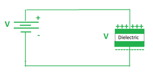
Fig 1. A capacitor is connected to a battery.
Later we can remove the battery from the capacitor and then place a load resistor into that circuit this would lead to the capacitor acting as a battery in a closed circuit and the current would flow from the positively charged terminal of the capacitor to the negatively charged terminal of the capacitor. And with time the capacitor would lose all of its charges. The time period in which it loses all of its charges is called the discharging period of the capacitor.
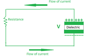
Fig 2. Discharging phase of a capacitor.
Thus we can say that a capacitor is a device that can store charge and in turn energy in itself.
Capacitance of a conductor
Consider a capacitor whose positive and negative plates hold +q and -q charge respectively. A DC voltage source is applied across it which gives it a potential difference of V across the plates. Now as we know,
Q ∝ V
Putting a constant C in this relation.
Q = CV.
Note: The capacitance of every material is unique and its SI unit is Farad (F).
Parallel Plate capacitor
Consider a given setup of two plates that are connected across a battery, the arrangement is such that both the plates have the same physical dimensions and they are both placed parallel to each other and separated by some distance. The separation between the two plates is filled with some dielectric. The two plates are also oppositely charged since the plate connected to the positive terminal acquires a positive charge and the plate connected to the negative terminal acquires a negative charge
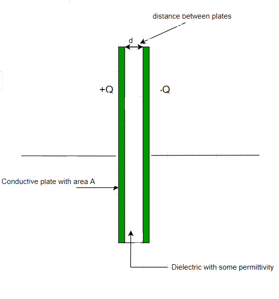
Fig 3. A simple parallel plate capacitor.
In our case the area of both the plates is A and the charge on them is +Q and -Q. Also, the distance between them is given by d which is negligibly small when compared to the area of the plates so we can say that d<<A.
Now since d<<A.
Therefore both the plates can be considered as infinite plane sheets.
The surface charge density of positively charged plate can be given by
.
The surface charge density of negatively charged plate can be given by
.
Let’s assume that the parallel plate capacitor divides the plates into three regions in such a way that,
- The region to the left of the positively charged plate is Region 1.
- The region in the middle of the two plates is region 2.
- And the region to the right of the negatively charged plate is region 3.
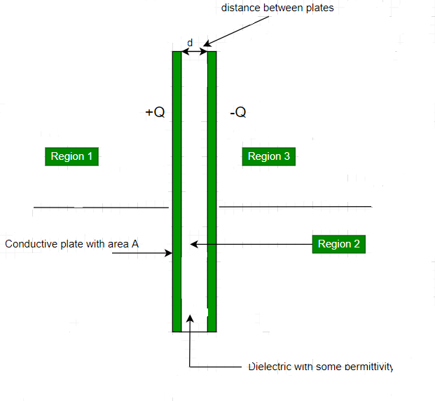
Fig4. The plane gets divided into three regions.
Now let’s calculate the electric fields in each of the three regions separately.
- Region 1:
Using Gauss’s law the electric field generated by an infinite sheet is given by:-
.
The electric field generated by both the plates in region 1 is the same in magnitude and opposite in direction.
E = E1 + E2
.
E = 0.
- Region 2:
In this case we calculate the electric field in between the two plates.
Here the magnitude and the direction of the electric field are the same. So the generated electric field is given by:-
E =

.
- Region 3:
This region is to the right of the negatively charged plate.
The electric field in this case is given by
E =
.
E = 0.
Now the expression for capacitance is given as:
. ⇢ (1)
The value of potential difference V can be found using the formula,
V = E × d.
. ⇢ (2)
So the capacitance of the parallel plate capacitor can be given by
From (1) and (2),
.
Sample Questions
Question 1: A parallel plate capacitor is placed in the air. Find its capacitance if the area of each plate is 100 cm2 and the separation between the plates is 1 cm.
Solution:
The capacitance of the parallel plate capacitor can be given as,
Here A = 100 ×10-4 m2, d= 10-2 m.
C =

C = 8.85 × 10⁻¹² F.
Question 2: A capacitor of area 100 cm^2 generates a capacitance of 17.7 × 10⁻¹¹ F . Find out the separation between the plates of this capacitor.
Solution:
C =
Here A = 100 × 10-4 m , C = 17.7 × 10⁻¹¹ F
17.7 × 10-11 =

d = 5 × 10⁻⁴ m.

Question 3: The area of a parallel plate capacitor is doubled and separation between the plates is halved to find out the change in its capacitance.
Solution:
C1 =

According to question,
d2 =

A2 = 2 A1
C2 =

C2 = 4

C2 = 4 C1
Question 4: A parallel plate capacitor with a plate area of 100 cm2 and separation between the plates of 1 cm is placed in the air is given a voltage of 1000V Find its energy
Solution:
The capacitance of the parallel plate capacitor can be given as,
C =

Here A = 100 × 10-4m2, d = 10-2 m
C =

C = 8.85 × 10⁻¹² F.
The energy of this capacitor can be calculated by using the expression
U = 1/2 CV2
U =

U = 4.425 × 10⁻⁶ J
Question 5: The capacitance of a parallel plate capacitor is 4.425 × 10⁻¹² F. The separation between the plates is 1cm. Find the area of each plate.
Solution:
The capacitance of the parallel plate capacitor can be given as
C =
Here C = 4.425 × 10⁻¹² F , d= 10-2 m
4.425 × 10-12 = 8.85 × 10⁻¹² × A/10-2 .
A =

A = 5 × 10⁻³ m2

Question 6: A parallel plate capacitor is placed in the air. Find its capacitance if the area of each plate is 100 cm2 and the separation between the plates is 1 cm. If a voltage of 100 V is supplied how much charge will the capacitor store?
Solution:
the capacitance of the parallel plate capacitor can be given as
C =

Here A = 100 × 10-4 m2, d = 10-2m.
C =
C= 8.85 × 10⁻¹² F.
The charge on a Capacitor is given by
Q = CV.
Q = 8.85 × 10-12 × 100 C.
Q = 8.85 × 10⁻¹⁰
Question 7: The separation between the plates of a parallel plate capacitor is filled with a material of Relative permittivity five times that of air find out its capacitance if the separation between the plates is 1 cm and the area of each plate is 200cm2.
Solution:
the capacitance of the parallel plate capacitor can be given as
C =
Here A = 200 × 10-4 m2, d = 10-2m .
ε = 5 × 8.85 × 10-12 .
C =
.
C = 8.85 × 10⁻¹¹F .

Capacitors in Series and Parallel
Capacitors are special devices that can hold electric charges for instantaneous release in an electric circuit. We can easily connect various capacitors together as we connected the resistor together. The capacitor can be connected in series or parallel combinations and can be connected as a mix of both.
In this article, we will learn about capacitors connected in series and parallel, their examples, and others in detail.
Capacitor Definition
Capacitor is defined as follows:
Capacitors are electrical devices that store electrical energy in the circuit developed due to the opposite charges deposited on each plate due to the electrical field.
Capacitance Definition
Capacitance is defined as the charge-storing capacity of an electrical device. It is given by C = q/V where C is capacitance, q is charge and V is voltage. The unit of Capacitance is Farad denoted by “F”.
How are Capacitors Connected?
We can arrange for various capacitors to be connected with each other and the total capacitance of all the capacitors can be defined as the ratio of the total charge held by the capacitor and the total voltage applied in the circuit. This can be represented as,
Ceq = Q/V
where C is Capacitance
Q is Charge
V is Voltage
Now we can connect various capacitors in two configurations and the two configurations are,
- Series Combination
- Parallel Combination
Now let’s learn more about these combinations in detail.
Series Combination of Capacitors
In the figure given below, three capacitors are connected in series with the battery of voltage V. Note that in the figure, opposite charges of equal magnitude flow and get accumulated on the plates of the capacitor. Conservation of charge principles requires that the charge that is accumulated on the plates of the capacitor must be equal in magnitude. The end result is a combination that resembles a single capacitor with an effective plate separation that is greater than that of individual capacitors, this equivalent capacitor is shown in the figure below. Large plate separation means smaller capacitance.
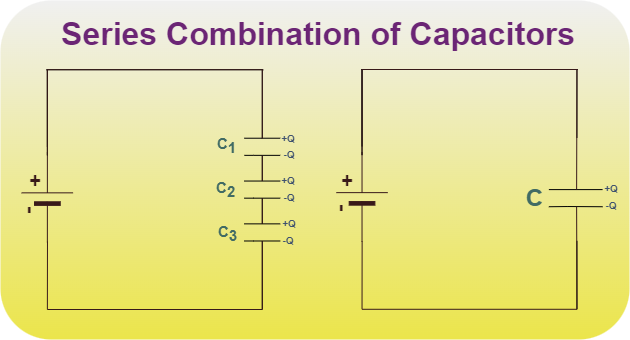
The derivation of relation for capacitors in series is explained below:
The relation for capacitance is given by,
C = Q/V
It can be rewritten as,
V = Q/C
The voltages across individual capacitors will be,
V1 = Q/C1 , V2 = Q/C2, V3 = Q/C3
The total voltage across all the capacitors will be,
V = V1 + V2 + V3
substituting the expressions for individual voltages,
V = Q/C1 +Q/C2 + Q/C3
Let the equivalent capacitance be C,
Q/C = Q/C1 +Q/C2 + Q/C3
Upon Simplifying the above equation, the relation becomes,
In general for capacitors C1, C2, C3,…


Example of Capacitor Connected in Series Combination
Let’s take four capacitors of capacitance 2 μF, 6 μF, 8 μF, and 3 μF connected in series then find the equivalent capacitance of the circuit.
Solution:
Given
- C1 = 2 μF
- C2 = 6 μF
- C3 = 8 μF
- C4 = 3 μF
Equivalent capacitance of the capacitor in Parallel Combination
1/Ceq = 1/C1 + 1/C2 + 1/C3 + 1/C4
1/Ceq = 1/2 + 1/6 + 1/8 + 1/3
1/Ceq = (12 + 4 + 3 + 8)/24 = 27/ 24
Ceq = 24/27 μF
Thus, the equivalent capacitance of the capacitor connected in series is, 24/27 μF
Parallel Combination of Capacitors
In the figure given below, three capacitors C1, C2, and C3 are connected in parallel to a voltage source of potential V. Deriving the equivalent capacitance for this case is relatively simple. Note that the voltage across each capacitor is the same as that of the source since it is directly connected to the source. Thus capacitors have the same charges on them as they would have if connected individually to the voltage source.
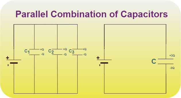
The derivation of the relation for Capacitors in Parallel is explained below:
Let’s say the total charge on the capacitors is Q,
Q = Q1 + Q2 + Q3
Q = Q1 + Q2 + Q3
CV = C1V + C2V + C3V
C = C1 + C2 + C3
Also, Read
Example of Capacitor Connected in Parallel Combination
Let’s take four capacitors of capacitance 2 μF, 6 μF, 8 μF, and 3 μF connected in parallel then find the equivalent capacitance of the circuit.
Solution:
Given
- C1 = 2 μF
- C2 = 6 μF
- C3 = 8 μF
- C4 = 3 μF
Equivalent capacitance of the capacitor in Parallel Combination
Ceq = C1 + C2 + C3 + C4
Ceq = 2 + 6 + 8 + 3
Ceq = 19 μF
Thus, the equivalent capacitance of the capacitor connected in parallel is, 19 μF
Some Important Points
- The capacitance of N identical capacitors connected in series combination,
1/Ceq = 1/C + 1/C + 1/C +…+ 1/C(n times)
1/Ceq = N/C
Ceq = C/N
- The capacitance of N identical capacitors connected in parallel combination,
Ceq = C + C + C +…+ C(n times)
Ceq = NC
Examples on Combination of Capacitors
Example 1: Find the equivalent capacitance for the system of capacitors 3 pF, 5 pF, and 10 pF added in parallel combination.
Solution:
Formula for Combintion of Capcitor in Parallel Combination is,
C = C1 + C2 + C3
Given,
- C1 = 3 pF
- C2 = 5 pF
- C3 = 10 pF
Substituting these values we get,
C = 3 + 5 + 10
C = 18 pF
Thus, the equivalent capacitance of given capacitor is 18 pF
Example 2: Find the equivalent capacitance for the system of capacitors 2 pF, 2 pF, and 4 pF added in a series combination.
Solution:
Formula for Combintion of Capcitor in Series Combination is,
Given,
- C1 = 2 pF
- C2 = 2 pF
- C3 = 4 pF
Substituting these values we get,
C = 4/5
Thus, the equivalent capacitance of given capacitor is 4/5 pF.


Example 3: Find the equivalent capacitance for the system shown in the figure below.
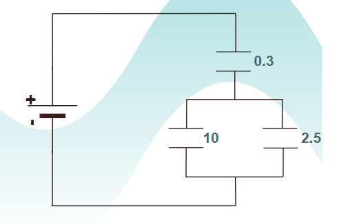
Solution:
Formula for Combintion of Capcitor in Parallel and Series Combination is,
- C = C1 + C2 + C3 + ….
Given,
- C1 = 10 μF,
- C2 = 2.5 μF
C = C1 + C2
C = 10 + 2.5
C = 12.5
C = 0.29
Thus, the equivalent capacitance of given system is 0.29 μF


Example 4: If the equivalent capacitance for the system of capacitors x, 5 pF, and 10 pF added in parallel is 23 pF. Find the value of x.
Solution:
Formula for Combintion of Capcitor in Parallel Combination is,
C = C1 + C2 + C3
Given,
- C1 = x
- C2 = 5 pF
- C3 = 10 pF
Substituting these values we get,
23 = x + 5 + 10
x = 23 – 15 = 8 pF
x = 8 pF
Thus, the required capacitance of given capacitor is 8 pF.
Example 5: If the equivalent capacitance for the system of capacitors 3 F, 6 F, and x F added in parallel is 6/7 F
Solution:
Formula for Combintion of Capcitor in Parallel Combination is,
Given,
- C = 6/7 F
- C1 = 2 F
- C2 = 2 F
- C3 = x F
Substituting these values we get,
7/6 = (2+1)/6 + 1/x
7/6 = 3/6 + 1/x
7/6 – 3/6 = 1/x
4/6 = 1/x
2/3 = 1/x
x = 3/2
Thus, the value of unknown resitance x is 3/2 F.

FAQs on Capacitance
Q1: What is Capacitor?
Answer:
Capacitors are electrical instruments that are used to store energy in the form of charge in an electric circuit.
Q2: What is Capacitance?
Answer:
Capacitance is the property of any material to store charges. And the material that stores charges are called a capacitor.
Q3: How to store Energy in Capacitor?
Answer:
The energy in the capacitor is stored as Electrical Potential Energy. The change in the voltage of the capacitor results in a change in its potential energy.
Q4: What is the Capacitance formula?
Answer:
The capacitance formula of the capacitance is,
C = q/v
where,
q is the charge inside the capacitor
v is the voltage of the capacitor
Energy stored in a Capacitor
Capacitors are used in almost every electronic device around us. From a fan to a chip, there are lots of capacitors of different sizes around us. Theoretically, the basic function of the capacitor is to store energy. Its common usage includes energy storage, voltage spike protection, and signal filtering. It was invented by a German scientist, Ewald Georg von Kleist, in 1745. Physically, a capacitor is just two conductors which are separated by an insulator. They are able to hold a charge which gives rise to a lot of their properties. Let’s study these properties in detail.
Capacitors and Capacitance
A capacitor is a system of two charges that are separated by an insulator. Let’s say the two conductors have a charge of Q1 and Q2 and potential V1 and V2. Usually, the charges are Q and -Q. The electric field in this region is proportional to the charge on the surface of capacitors. The figure below shows two conductors with charges Q and -Q on them. These conductors are separated by an insulator.
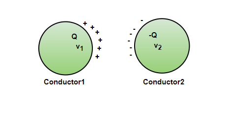
Now it is known that potential is nothing but the work done to bring the charge from the infinite to the present position. In this way, the potential also becomes proportional to the charge on the conductors. This means that the ratio of charge and potential is constant. The ratio is termed capacitance.

Although any shape and size works for making a capacitor, in real life most of these capacitors are cylindrical. While doing calculations and for the symbol, the capacitor is denoted as a parallel plate capacitor.
Parallel Plate Capacitor
A parallel plate capacitor consists of two large parallel planes separated by a small distance. Most of the time, the medium between the plates is considered to be a vacuum, but it can be any insulator material. The figure shows the diagram of a parallel plate capacitor that is connected to a battery.
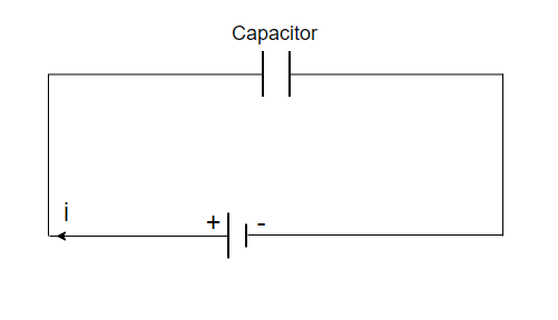
Energy stored in a Capacitor
When a battery is connected across the plates of a capacitor, the current charges the capacitor, leading to the accumulation of the charges on the opposite plates. As the charges accumulate, the potential difference between the plates starts increasing. Let’s say the capacitance of the capacitor is “C”, it was uncharged initially. Now, after being connected to the battery, let’s say there is a potential difference, “V” that develops between the plates. Consider “q” as the charge on the plates at that time. Then,
q = CV
Work done to bring the charge from infinity to the potential of “V” is given by,
W = qV
Suppose the battery delivers a charge of “dq” to the plates while keeping the potential constant. Then,
W = dq.V = 
In this way, a total charge “q” is transferred from the battery to the capacitor. Then, the work done will be given by

So, the energy stored in the capacitor is,

Using the previous relationship, q = CV
Energy can be re-written as,

Using relationship, C= q/V
Energy can be written as,

Therefore, the three formulae obtained for Energy stored in a capacitor,

Sample Problems
Question 1: Find the capacitance if a charge of 3C and potential of 9V is maintained on plates.
Solution:
The relation for capacitance is given by,
q = CV
Given: q = 3C and V = 9V
q = CV
⇒ 3 = C(9)
⇒
= C
C = 0.333F
Question 2: Find the capacitance if a charge of 18C and the potential of 3V is maintained between the plates.
Solution:
The relation for capacitance is given by,
q = CV
Given: q = 18C and V = 3V
q = CV
⇒ 18 = C(3)
⇒ 6 = C
C = 6F
Question 3: Find the capacitance if a charge of 1C and the potential of 2V is maintained between plates.
Solution:
The relation for capacitance is given by,
q = CV
Given: q = 1C and V = 2V
q = CV
⇒ 1 = C(2)
⇒ 0.5 = C
C = 0.5F
Question 4: Find the energy stored in the capacitor of 12pF which is connected to a battery of 10V.
Solution:
The relation for energy stored in a capacitor is given by,
Given: C = 12pF and V = 10V


Question 5: Find the energy stored in the capacitor which has a charge of 9 x 10⁻⁵C and is connected to a battery of 10V.
Solution:
The relation for energy stored in a capacitor is given by,
Given: q = 9 x 10⁻⁵ and V = 10V


Question 6: Find the energy stored in the capacitor of 3pF which has a charge of 9 x 10⁻⁵C.
Solution:
The relation for energy stored in a capacitor is given by,
Given: q = 9 x 10⁻⁵ and C = 3 x 10-12

Question 7: A capacitor of capacitance “C”, is first connected to a battery of voltage V and fully charged, then it is connected to a battery of voltage 2V. Find the electrostatic energy gained/lost in this process.
Solution:
First, the capacitor is connected to a battery of the potential V.
Energy of the capacitor after full charge,
E1 =
After it is connected to another battery,
E2 =
⇒E2 =
Energy change in this process = E2 – E1
=
=
Since, the energy change is positive. Electrostatic energy was gained in the process.


0 Comments