
CBSE Class 12 Physics Notes
Chapter 1 – Electric Charges and Fields
The first chapter in Class 12 Physics is Electric Charges and Fields. In this chapter, electric charge is introduced once again to the students after class 9, but this time the study of charge is well-detailed and quite extensive. This chapter is the first chapter of electrostatics, i.e., the study of static charge, in which students study static charge and its various effects on other things, Coulomb’s law, and many more things, which are listed as follows:
- Electric Charge
- Conductors and Insulators
- Charging by Induction
- Basic Properties of Electric Charge
- Coulomb’s Law
- Electric Field
- Electric Field Lines
- Electric Flux
- Electric Dipole
- Continuous Charge Distribution
- Gauss’s Law
- Applications of Gauss’s Law
Unit of Electric Charge
Electric charge is the fundamental property of matter. Various properties are explained by the electric charges. So it is very important to note the unit of electric charge and other parameters of the electric charge. In this article, we will learn about electric charge its definition, and the units of electric charge in detail.
Electric Charge
Electric charge is that property of matter which causes the matter to experience a certain force when placed in an electric field. Static charges produce Electric Field and when these charges start to move and become dynamic, they produce a magnetic field as well, moving charge is responsible for the production of electricity as well, to be precise, it is the movement of electrons that produces electricity.
Electric Charge Formula
If the charge flowing inside a circuit producing electric current is needed to be calculated, the formula used for the same will be,
q = I × T
where,
I is the current flowing inside the circuit
T is the time for which the current is flowing.
SI Unit of Electric Charge
Electric Charge can be measured in various units and the SI unit for measuring Electric Charge is Coulomb, which is represented by ‘C’. The value present of a single charge is 1.6 × 10⁻¹⁹C i.e. both proton and electron have a charge equal to the magnitude 1.6 × 10⁻¹⁹C
One coulomb is defined as the amount of charge that passes through an electrical conductor in one second which carries one-ampere current.
Other Electric Charge Units
Electric Charge is measured in various units some of the other units of electric charge are,
| Symbol of Unit | Name of Unit | Context(Used) | Prefixes |
|---|---|---|---|
| abc coulomb | ab C | EMU | SI |
| stat coulomb | Stat C | EMU | SI |
| Franklin | f | standard | SI |
| Planck charge | – | Planck | SI |
| Electron | e | atomic | SI |
Other Units of Electrical
Electrical properties are widely used in science and some of the units that are used to measure various electrical properties are,
| Electrical Parameters | Symbol | Unit |
|---|---|---|
| Voltage | V | volt |
| Current | I | Ampere |
| Resistance | R | Ohm |
| Charge | Q | Coulomb |
| Capacitances | C | Farad |
| Inductance | L or H | Henry |
| Impedance | Z | Ohm |
| Power | W | Watts |
Definie 1 Coulomb charge
1 Coulomb of charge can is defined as the amount of charge transferred in one second from a wire carrying current equal to one Ampere.
Types of Electric Charge
There are only two types of electric charges,
- Positive Charge
- Negative Charge
They both have the same amount of charge present on them, but with opposite signs.
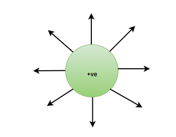
Positive Charge
Positive charges are also known as Protons and the electric field lines come out of the positive charge. The charge present on a proton is +1.6 × 10⁻¹⁹C. If an object is positively charged, it can be concluded that the object has more protons than electrons.
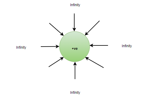
Negative Charge
Negative charges are also known as electrons. The electric field lines come from infinity inside a negative charge. The amount of charge present on an electron is -1.6 × 10⁻¹⁹C. If an object is known to be negatively charged, that means that the object has more electrons than protons.
Note:
- Like charges repel each other
- Unlike charges attract each other
.png)
Coulomb’s Law
Coulomb’s Law is used to define the Force between two charges. Two charges can either have a force of attraction or a force of repulsion between them.
Let’s say that there are two charges q1, and q2 placed at a distance of ‘r’ between them, then the force between them will be defined as,
where,
is a ConstantHere, εo = 8.854× 10⁻¹² C2/N-m2
The force between two charges q1 and q2 when they are placed in any other medium than Free Space,
where,
ε is Absolute permittivity of the free space
If the ratio of the force in the free space and force in the medium is taken out, the relationship between absolute permittivity and relative permittivity (εr) is found,
ε/εo = εr
εr is Relative permittivity or Dielectric constant
Also, Check Coulomb’s Law
Read More
Solved Examples on Electric Charges
Example 1: How many electrons are present in 1 Coulomb of charge?
Solution:
In a single electron, charge is equal to 1.6 × 10⁻¹⁹C
1.6× 10⁻¹⁹C = 1 electron
1C = 1/(1.6 × 10-19) electrons
1C = 6.25 × 10¹⁸ electrons
Example 2: How many Protons are present in 10 C of charge?
Solution:
According to the Quantization of charge,
Q = ne
Q = 10 C
n = number of protons
e = 1.6 × 10⁻¹⁹C10 = n × 1.6× 10⁻¹⁹
n = 625 × 1017 protons
Example 3: In a system, the charges present are +5C, -7C, +1C, +9C, -15C. What is the total charge on the system?
Solution:
According to the Additivity property of Electric charges,
Q = q1+ q2+ q3+ q4+ q5
Q = +5C + (-7C) + 1C+ 9C+ (-15C)
Q = -7C
Example 4: Two charges +5C and +3C are placed at 1 meter apart in Free Space. Find the Force acting on them, and state the type of force as well.
Solution:
Force acting on +5C and +3C in free space is given by,
Since, the charge +5C and +3C are alike in nature, i.e. they are both positive, hence, the force acting between them is the Repulsive Force.
FAQs on Electric Charge
Question 1: Define electric charge.
Answer:
Electric charge is the fundamental property of the particles which is responsible for the elctromagnetic properties of the elements.
Question 2: What are the types of electric charges?
Answer:
Two types of electric charges are,
- Positive charge
- Negative charge
Question 3: What is the SI unit of Electric Charge?
Answer:
Electric Charge is measured in various units and the SI unit of electric charge is Coulomb.
Question 4: What is the Formula to find the Electric Charge?
Answer:
The Formula to find the Electric Charge is,
Q = I×t
where,
I is the current
t is the time taken
Question 5: Is Electric Charge a scalar quantity or a vector quantity?
Answer:
Electric charge is a Scalar quantity and this means that electric charge has magnitude but no direction. The additivity property of electric charge is a good way to prove that charges are scalar in nature. The algebraic sum do not take into account the directions of any charge placed in the system.
* Conductors and Insulators
When humans remove synthetic clothing or sweater, especially in dry weather, he or she often sees a spark or hear a crackling sound. With females’ clothing like a polyester saree, this is essentially observed. Another example is Lightning a common form of electric discharge that seen in the sky during thunderstorms, the sensation of being electric shock while opening a car door or while grabbing a bus’s iron bar after sliding off our seats.
The cause of these sensations is the discharge of electric charges that have collected as a result of rubbing insulating surfaces. This is related to static electricity generation. Anything that does not move or change through time is referred to as static. The study of forces, fields, and potentials coming from static charges is known as electrostatics.
Conductors
A metal rod brushed with wool in the hand will not exhibit any signs of being charged. A metal rod with a wooden or plastic handle, on the other hand, exhibits symptoms of charging when rubbed with wool without touching its metal section. Assume one end of a copper wire is connected to a neutral pith ball and the other end is connected to a negatively charged plastic rod. It is observed that the pith ball will acquire a negative charge. When a comparable experiment is carried out with a nylon thread or a rubber band, no charge is transferred from the plastic rod to the pith ball.
Some materials readily enable electricity to pass through them, whereas others do not. Conductors are materials that allow electricity to flow freely through them. They have comparatively free-moving electric charges (electrons) inside the material. Conductors include metals, human and animal bodies, and the ground itself.
Electrical circuits and equipment benefit from earthing as a safety measure. A big metal plate is placed deep in the soil, and thick wires are dragged from it; these cables are utilized in buildings to earth near the mains supply. Our homes’ electrical wiring consists of three wires: live, neutral, and earth. The first two carry electric current from the power plant, while the third is earthed by being connected to the buried metal plate. The earth wire is connected to the metallic body of electric equipment such as electric irons, refrigerators, and televisions. When a malfunction occurs or a live wire comes into contact with the metallic body, the charge flows to the earth without destroying the appliance or injuring humans; this would have been unavoidable otherwise because the human body is a conductor of electricity.
Applications of Conductor
Conductors are quite handy in a variety of situations. They’re useful in a variety of situations. As an example,
- Mercury is a frequent component of thermometers used to measure body temperature.
- Aluminum is used in the manufacture of food-storage foils. It’s also used to make fry pans that can hold heat for a long time.
- Iron is a typical heat-conducting material used in car engine production.
- The iron plate is made of steel to quickly absorb heat.
- Conductors are used in automobile radiators to transfer heat away from the engine.
Examples of Conductors
- Silver is the most effective conductor of electricity. However, because silver is expensive, it is not used in industry or for energy transmission.
- Copper, brass, steel, gold, and aluminum are excellent electrical conductors. In the shape of wires, we use them in electric circuits and systems.
- Mercury is a great conductor of liquids. As a result, this material is used in a variety of instruments.
- Because the atoms are so far apart, gases are poor conductors of electricity. As a result, they can’t conduct electrons.
Insulators
Most non-metals, such as glass, porcelain, plastic, nylon, and wood, have a high resistance to the transmission of electricity. They are called insulators. Insulators are materials that prevent electrons from freely flowing from one element’s particle to another. If a charge is applied to such an element at any point on the surface, the charge remains in the same place and does not spread throughout the surface. Charging by rubbing (for some elements, with the help of suitable materials) and charging by induction are two typical methods for charging such components.
When a charge is transmitted to a conductor, it quickly becomes charged. Dispersed across the conductor’s whole surface If, on the other hand, some When a charge is applied to an insulator, it remains stationary. This material property explains why a nylon or plastic comb is preferred. When combing dry hair or stroking it, it becomes electrified, while a metal piece does not. The charges on metal pass through our bodies to the ground. Both the ground and the body are electrical conductors.
Applications of Insulators
- Insulators are used all around the world because they prevent electron flow. Among the most common applications are:
- Thermal insulators prevent heat from moving from one location to another. As a result, they’re used to making thermoplastic bottles. They’re also utilized to fireproof walls and ceilings.
- Sound insulators are useful for controlling noise levels since they absorb sound well. As a result, we employ them to make buildings and conference spaces noise-free.
- Electrical insulators obstruct electron flow and current flow via them. As a result, we frequently utilize them in circuit boards and high-voltage systems. Electric wire and cables are also coated with them.
Examples of Insulators
- Because of its high resistivity, glass is the best insulator.
- Plastic is a good insulator and is used to make a variety of items.
- Rubber is commonly utilized in the manufacture of tyres, fire-resistant clothing, and shoes. This is due to the fact that it is an excellent insulator.
Difference between Conductors and Insulators.
Conductor | Insulators |
|---|---|
A conductor is a material that permits current to flow freely through it. | Insulators prevent current from flowing through them. |
Electric charge exists on the surface of conductors. | Electric charges are absent in the insulator. |
Conductors don’t store energy when kept in a magnetic field. | Insulators store energy when kept in a magnetic field. |
The thermal conductivity ( heat allowance) of a conductor is very high. | Insulators store energy when kept in a magnetic field. |
Conductors don’t store energy when kept in a magnetic field. | Insulators store energy when kept in a magnetic field. |
The thermal conductivity ( heat allowance) of a conductor is very high. | The thermal conductivity of an insulator is very low. |
The resistance of a conductor is very low. | The resistance of the insulator is very high. |
Sample Questions
Problem 1: What do you mean by Charging by Friction?
Solution:
The charging by friction method includes rubbing one particle against another, causing electrons to move from one surface to the next. This procedure can be used to charge insulators.
Different types of atoms and atom combinations make up material objects. Various items have different electrical characteristics due to the existence of different atoms in them. Electron affinity is one of these properties. Simply described, electron affinity is a feature that describes how much a substance cares about electrons. If a substance’s atoms have a high electron affinity, the material will have a strong affection for electrons as well. As one of the most prevalent types of charging, turboelectric charging, commonly known as charging by friction or rubbing, this property of electron affinity will be crucial.
Problem 2: If 109 electrons move out of a body to another body every second, how much time is required to get a total charge of 1 C on the other body?
Solution:
In one second 109 electrons move out of the body. Therefore, the charge given out in one second is
1.6 × 10–19 × 109 C = 1.6 × 10⁻¹⁰ C.
The time required to accumulate a charge of 1 C can then be estimated to be
1 C / (1.6 × 10⁻¹⁰ C/s)
= 6.25 × 10⁹ s = 6.25 × 10⁹ / (365 × 24 × 3600) years
= 198 years.
Thus, to collect a charge of one coulomb, from a body from which 109 electrons move out every second, we will need approximately 200 years. One coulomb is, therefore, a very large unit for many practical purposes. It is, however, also important to know what is roughly the number of electrons contained in a piece of one cubic centimeter of material. A cubic piece of copper of side 1 cm contains about 2.5 × 1024 electrons.
Problem 3: Does pure water conduct electricity? If not, what can we do to make it conducting?
Solution:
No, pure water doesn’t conduct electricity. When salt is dissolved in pure water, it conducts electricity as it provide it with ions needed to conduct electricity.
Problem 4: How much positive and negative charge is there in a cup of water?
Solution:
Let us assume that the mass of one cup of water is 250 g. The molecular mass of water is 18 g. Thus, one mole (= 6.02 × 10²³ molecules) of water is 18 g. Therefore, the number of molecules in one cup of water is (250/18) × 6.02 × 1023. Each molecule of water contains two hydrogen atoms and one oxygen atom, i.e., 10 electrons and 10 protons. Hence, the total positive and total negative charge has the same magnitude. It is equal to
(250/18) × 6.02 × 1023 × 10 × 1.6 × 10–19 C
= 1.34 × 10⁷ C.
Problem 5: What is Coulomb’s Law?
Solution:
According to Coulomb’s law, the force of attraction or repulsion between two charged things is directly proportional to the product of their charges and inversely proportional to the square of the distance between them. It acts along the line that connects the two charges that are regarded to be point charges.
Coulomb studied the force between two point charges and found that it is inversely proportional to the square of the distance between them, directly proportional to the product of their magnitudes, and acting in a line that connects them.
Charging by Induction
Charging by Induction- A spark or crackling sound emerges when our synthetic garments or sweaters are removed from our bodies, especially in dry weather. This is virtually unavoidable with feminine apparel, such as polyester sarees. Lightning, in the sky during thunderstorms, is another case of electric discharge. It is an electric shock always felt while opening a car door or grabbing the iron bar of a bus after sliding out of our seats.
What is Induction?
The cause of these sensations is the discharge of electric charges that have collected as a result of rubbing insulating surfaces. This is due to static electricity generation. Anything that does not have movement or change with time is referred to as static. The study of forces, fields, and potentials coming from static charges is known as Electrostatics.
Electrical neutrality refers to the presence of an equal amount of positive and negative charges in most bodies. To charge a neutral body, the balance of positive and negative charges has to be changed. The methods of altering the charge balance of a neutral body are:
- Friction
- Conduction
- Induction
Charging by Friction
The charging by friction method includes rubbing one particle against another, causing electrons to move from one surface to the next. This procedure can be used to charge insulators.
Charging by friction
- Different types of atoms and atom combinations in material objects give rise to various electrical characteristics.
- Electron affinity is a property that describes a substance’s affinity for electrons.
- Materials with high electron affinity strongly attract electrons.
- Turboelectric charging, or charging by friction, relies on electron affinity.
- For example, rubbing a rubber balloon with animal fur brings their atoms close together, causing their electron clouds to interact.
- Rubber atoms, with a stronger affinity for electrons, steal them from the fur, leading to both materials becoming charged.
- Similarly, when two glass rods rubbed with wool or silk cloth are brought together, they repel each other, along with the strands of cloth.
- However, the glass rod and the cloth are attracted to each other due to their differing electron affinities.
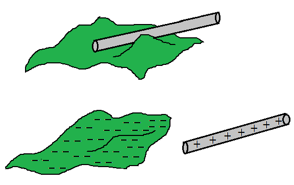
Charging by Conduction
- Charging by conduction occurs when a charged particle comes into contact with a neutral conductive medium.
- . Charges are transmitted from the charged substance to the neutral conductor. This approach can be used to charge conductors.
Charging by Conduction.
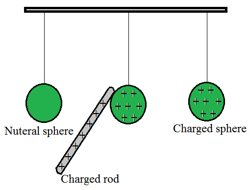
- Conduction charging happens when a charged object touches a neutral object.
- For instance, if a positively charged aluminum plate contacts a neutral metal sphere, the sphere becomes charged.
- Electrons from the neutral sphere move towards the positively charged plate.
- This movement causes the sphere to acquire a positive charge.
- Consider the case of a negatively charged metal spherical being pressed against the top plate of a neutral needle electroscope. When the metal sphere makes contact with the neutral electroscope, it charges it.
- Finally, imagine that an uncharged physics scholar is standing on an insulating platform when a scholar comes into contact with a negatively charged Van de Graaff generator causes the neutral physics scholar to become charged.
- Each of these cases includes a charged object making contact with a neutral object. In contrast to induction charging, which involves bringing the charged object close to but never touching the object being charged, conduction charging entails physically connecting the charged object to the neutral object.
- Charging by conduction is sometimes known as charging by touch since it involves contact.
Charging By Induction
Induction charging is a charging method in which a neutral object is charged without actually touching another charged object. The charged particle is held near a neutral or uncharged conductive material that is grounded on a neutrally charged material. When a charge flows between two objects, the uncharged conductive material develops a charge with the polarity opposite that of the charged object.
(1) Charging by induction using a positively charged rod:
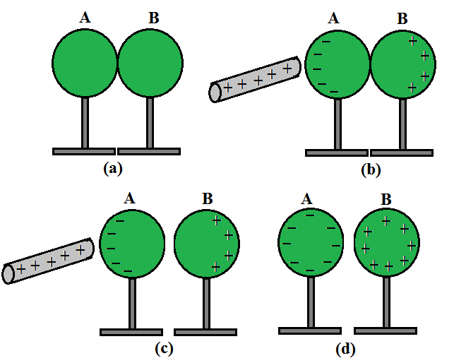
Charging by induction using a positively charged rod.
- Place two metal spheres, A and B, on insulating platforms and bring them together.
- Bring a positively charged rod close to one of the spheres, say A, but don’t let it touch it. The rod attracts the free electrons in the spheres. The rear surface of sphere B now has an excess of positive charge. Both types of charges are encased in metal spheres and are unable to escape. As a result, they live on the surfaces. The left surface of sphere A has a negative charge surplus, while the right surface of sphere B has a positive charge excess. On the left surface of A, not all the electron particles in the spheres have collected. Other electron particles are repelled by the negative charge that is building upon A’s left surface. Under the operation of the rod’s attraction force and the force of repulsion caused by the accumulated charges, equilibrium is achieved in a short period. The equilibrium situation is depicted in Fig. 1.4(b).
- Induction of charge is the name for the process, which occurs nearly quickly. The collected charges remain visible on the surface until the glass rod is held close to the sphere, as shown. When the rod is withdrawn, the charges are no longer affected by external forces and revert to their original neutral condition.
- As indicated in Figure separate the spheres by a modest distance while holding the glass rod near sphere A. (c). The two spheres are found to be charged in opposite directions and are attracted to each other.
- Take out the rod. As demonstrated in Figure the charges on spheres rearrange themselves (d). Separate the spheres completely now. As illustrated in Figure the charges on them are uniformly spread over them (e).
- The metal spheres will be equal and oppositely charged in this operation.
- This is known as induction charging. In contrast to charging through contact, the positively charged glass rod does not lose any of its charges.
(2) Charging by induction using a negatively charged rod:
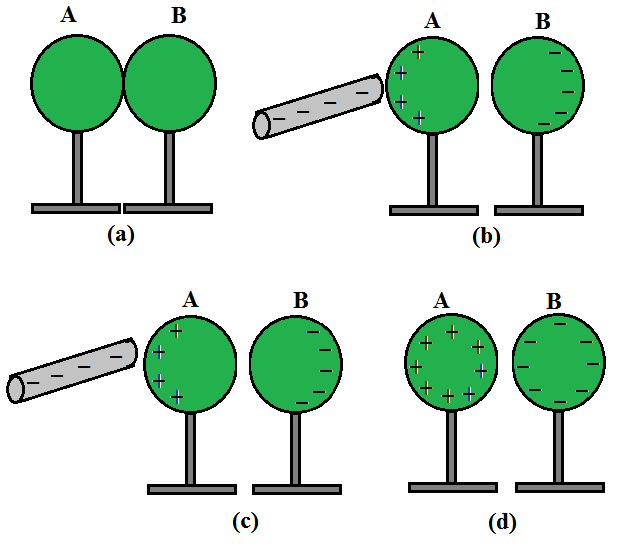
Charging by induction using a negatively charged rod.
- Consider two metal spheres A and B, which are touching in the illustration. Take a charged rod that is negatively charged. When a charged rod is kept close to the spheres, the repulsion between the charged rod’s electrons and the spheres causes electrons in the two-sphere system to move away.
- The electrons from sphere A are transported to sphere B as a result. Sphere A becomes positively charged and sphere B becomes negatively charged due to electron migration.
- As a result, the entire two-sphere system is electrically neutral. As illustrated, the spheres are then separated (avoiding direct contact with the metal). When the charged rod is removed, the charge is redistributed throughout the spheres, as indicated in the diagram.
Differences between Electrostatic and Electromagnetic Induction.
| S. no. | Electromagnetic Induction | Electrostatic Induction |
|---|---|---|
| 1. | Without any electrical connection, the formation of emf in a conductor due to the rate of change of current in a neighboring conductor. | Without any physical contact, the collection or redistribution of electric charges in a body caused by a neighboring charged body. |
| 2. | It is effective across great distances. | It is effective across short distances. |
| 3. | It’s because of the rate of change in charge flow. | It’s because of static charges. |
| 4. | In conductors, the effect is strongest. | In insulators, the effect is strongest. |
| 5. | The cause for this is due to the electric fields of the charges. | The cause is magnetic fields caused by moving charges. |
Law of Conservation of Charge
A charge is a characteristic of matter that causes it to create and experience electrical and magnetic effects. The underlying idea behind charge conservation is that the system’s overall charge is conserved. It can be defined as follows:
According to the rule of conservation of charge, the total charge of an isolated system will always remain constant. At any two time intervals, any system that is not exchanging mass or energy with its surroundings will have the same total charge.
When two objects in an isolated system each have a net charge of zero and one of the body transfer one million electrons with the other, the object with the surplus electrons will be negatively charged, while the object with the fewer electrons will have a positive charge of the same magnitude.
The total charge of the system has never changed and will never change.
Properties of Electric Charges
Additivity of Charges:
- In a system with two point charges q1 and q2 the total charge is determined by algebraically adding q1 and q2 similar to how real numbers are added.
- For a system with n charges ( q1,q2,q3,…qn) the total charge is calculated as ( q1+ q2+q3…qn).
- Charge, like mass, possesses magnitude but lacks direction.
- Unlike mass, which is always positive, charge can be positive or negative.
- When adding charges to a system, specific conventions must be followed to indicate the sign of each charge.
Conservation of Charge:
- The rule of conservation of charge states that the total charge of an isolated system remains constant over time.
- In an isolated system not exchanging mass or energy with its surroundings, the total charge remains the same at any two time intervals.
- For example, if two objects in an isolated system each have a net charge of zero and one transfers one million electrons to the other, the object gaining electrons becomes negatively charged, while the one losing electrons becomes positively charged.
- However, the total charge of the system remains unchanged throughout the process.
- This demonstrates the principle of charge conservation, where the total charge of an isolated system is constant and does not change over time.
Quantization of Electric Charge:
- All available charges are integral multiples of a basic unit of charge designated by e. As a result, the charge q on a body is always given by:
q = ne
Where n is any positive or negative integer.
The charge that an electron or proton carries is the basic unit of charge. The charge on an electron is assumed to be negative, the charge on an electron is written as –e, while the charge on a proton is written as +e.
Sample Problems
Problem 1: How much positive and negative charge is there in a cup of water?
Solution:
Let us assume that the mass of one cup of water is 250 g. The molecular mass of water is 18 g. Thus, one mole (= 6.02 × 10²³ molecules) of water is 18 g. Therefore, the number of molecules in one cup of water is (250/18) × 6.02 × 1023. Each molecule of water contains two hydrogen atoms and one oxygen atom, i.e., 10 electrons and 10 protons. Hence, the total positive and total negative charge has the same magnitude. It is equal to
(250/18) × 6.02 × 1023 × 10 × 1.6 × 10–19 C = 1.34 × 10⁷ C.
Problem 2: Compare the nature of Electrostatic and Gravitational Forces.
Solution:
Between two huge masses, a gravitational force acts. However, an electrostatic force is activated when two charged bodies come into contact.
Similarities:
- These two forces are central forces.
- Follow the law of inverse squares.
- They’re both long-range forces.
- Both forces are naturally conservative.
Dissimilarities:
- In nature, electrostatic force can be both attractive and repellent. In nature, gravitational force can only be attractive.
- The material medium between two charges affects the electric force between them. The material medium between huge bodies has little effect on gravitational force.
- Electric forces are extremely powerful (approximately 10 38 times stronger) than gravitational forces.
Problem 3: Why does Coulombs’ force act between two charges only in the line joining their centers?
Solution:
Because of the fundamental features of electrical charge, this is the case. Charges that are similar repel each other. Charges that are diametrically opposed attract each other.
The force of attraction or repulsion between two charges will be directed in the direction so that the force does the least amount of work. As a result of this requirement, the action is directed along the straight line connecting the two charges, which is the shortest distance between them.
Problem 4: If 109 electrons move out of a body to another body every second, how much time is required to get a total charge of 1 C on the other body?
Solution:
In one second 109 electrons move out of the body. Therefore, the charge given out in one second is
1.6 × 10–19 × 109 C = 1.6 × 10⁻¹⁰ C.
The time required to accumulate a charge of 1 C can then be estimated to be
1 C / (1.6 × 10⁻¹⁰ C/s) = 6.25 × 10⁹ s
= 6.25 × 10⁹ / (365 × 24 × 3600) years
= 198 years.
Thus, to collect a charge of one coulomb, from a body from which 109 electrons move out every second, we will need approximately 200 years. One coulomb is, therefore, a very large unit for many practical purposes. It is, however, also important to know what is roughly the number of electrons contained in a piece of one cubic centimeter of material. A cubic piece of copper of side 1 cm contains about 2.5 × 1024 electrons.
Problem 5: Write the differences between electrostatic and electromagnetic induction.
Solution:
Following are the differences between electrostatic and electromagnetic induction:
S. no. Electromagnetic Induction
Electrostatic Induction
1. Without any electrical connection, the formation of emf in a conductor due to the rate of change of current in a neighboring conductor. Without any physical contact, the collection or redistribution of electric charges in a body caused by a neighboring charged body. 2. It is effective across great distances. It is effective across short distances. 3. It’s because of the rate of change in charge flow. It’s because of static charges. 4. In conductors, the effect is strongest. In insulators, the effect is strongest. 5. The cause for this is due to the electric fields of the charges. The cause is magnetic fields caused by moving charges.
Basic Properties of Electric Charge
Electric Charges are fundamental in the universe. The presence of electric charges are not only seen in the field of science but also in the daily lives of human beings. For instance, rubbing dry hair with a ruler ends up making some hair strands stand up and this happens because electric charges are present everywhere in everything.
Types of Electric Charge
Electric Charge is the basic physical property of matter and due to this property, a force is experienced when kept in the field of electricity. Electric charges are of two types,
Positive Charge
Positive charges or protons have a charge of +1.6 × 10⁻¹⁹ Coulomb. A positive charge has its field lines emerging from within and going upto infinity.
Negative Charge
Negative charges or Electrons have a charge of -1.6 × 10⁻¹⁹ Coulomb. A Negative charge has its field lines coming from infinity.
The above example where hair strands start to attract to the ruler is due to electric charges. Similarly, rubbing a balloon on hair attracts hair to the balloon, in case two balloons are simultaneously rubbed, the balloons will start to repel each other, but they will attract the hair strands.
The rate of change of electric charge is known as Electric current,
I = q/t
Properties of Electric Charges
In order to look at the properties of electric charge, consider the electric charges to be really small, known as the Point charge. Point charges are smaller than the distance between them.
Additivity of Electric Charges
Electric charges when they are considered as point charges are scalar in nature. With that, it is important to note that charges can be point charges, but they are still positive and negative charges. The additive property of electric charges says that if there are n number of charges present inside, The total charge present will be the algebraic sum of the individual charges.
Q = q1+ q2+ q3+….. qn
Conservation of Charges
The Conservation of charges says that the charges are neither created not destroyed. They can be transferred from one body to another, but they cannot be created or destroyed. In an Isolated system, the charges are always conserved.
Quantization of Charge
According to the quantization of electric charge, Electric charges are defined as the Integral multiple of the charge present on them, hence, in any system, The charges will be,
q = ne
Where,
- n = Integer numbers
- e = value of the charge (1.6× 10⁻¹⁹ C)
Some Other Properties of Electric Charge
- Charge is a scalar quantity.
- Charge is transferable, they transfer from one body to another.
- Like charges repel each other and unlike charges attract each other.
- Charge is always associated with mass.
Also, Check
Sample Questions
Question 1: What are three basic properties of Charge?
Answer:
The three basic properties of Charge:
- Additivity of charges
- Quantization of charges
- Conservation of charge
Question 2: A polythene is rubbed against a woolen cloth, the charge developed on the woolen cloth is 7× 10⁻⁹C. What is the amount of charges transferred ?
Solution:
The Total charge present = 7 × 10⁻⁹ C.
q= 1.6 10-19 C.
Q = ne
7× 10-9= n × 1.6 × 10⁻¹⁹
n = 4.375 × 10¹⁰ C.
Question 3: Can Charge Exist without Mass?
Answer:
One of the basic properties of electric charge is that the Charge is always associated Mass. A charge does not exist without mass.
Question 4: How many electrons are present in one Coulomb?
Solution:
Charge on 1 Electrons = 1.6× 10⁻¹⁹C
Number of electrons present in 1 Coulomb = 1/(1.6× 10-19)
= 6.25 × 10¹⁸ Electrons.
Question 5: 5 different types of charges are present in an isolated system, the values of the charges are- +5nC, -6nC, +3nC, +4nC, +1nC. What is the total charge present in the system?
Solution:
Additivity property of electric charges is,
Q = q1+ q2+ q3+ q4+ q5
Q = (+5 – 6+ 3+ 4+ 1)nC
Q = 7nC
Question 6: If a system has 0 charge overall. Is it true that there are no charges present in the system?
Answer:
No, it is not true that the system would always have no charges present inside if the overall charge present inside is 0. There is a possibility that all positive charge cancels out all the negative charge and the overall system has 0 charge.
FAQs on Properties of Electric Charge
Is charge scalar or vector?
Charge is scalar quantity
How do like and unlike charges behave?
Like charges repel each other while unlike charges attract each other
What is meaning of quantization of charge?
Quantization of charge means charge can be expressed as integral multiple of smallest unit of charge
Do charges follow law of conservation?
Yes, charges follow the law of conservation
Coulomb’s Law
Coulomb’s Law is defined as a mathematical concept that defines the electric force between charged objects. Columb’s Law states that the force between any two charged particles is directly proportional to the product of the charge but is inversely proportional to the square of the distance between them. Let’s learn about Columb’s law in detail in this article.
Table of Content
What is Coulomb’s Law?
Coulomb’s law is a mathematical formula that describes the force between two point charges. When the size of charged bodies is substantially smaller than the separation between them, then the size is not considered or can be ignored. The charged bodies can be considered point charges.
Force of attraction or repulsion between two charged things is directly proportional to the product of their charges and inversely proportional to the square of the distance between them, according to Coulomb’s law. It acts along the line that connects the two charges that are regarded to be point charges.
Coulomb studied the force between two point charges and found that it is inversely proportional to the square of the distance between them, directly proportional to the product of their magnitudes, and acting in a line that connects them.
History of Coulomb’s Law
Charles Augustin de Coulomb a French mathematician in 1785 first describes a force between two charged bodies in mathematical equations. He stated that the charge bodies repel or attract each other accordingly based on their charge, i.e. opposite charge attracts each other and similar charge repels. He also states the mathematical formula for the force between them, which is called Columb’s Law.
Coulomb’s Law Formula (Scalar Form)
As we know, the force (F) between two point charges q1 and q2 separated by a distance r in a vacuum is,
Proportional to the product of the charges.
F ∝ q1q2
Inversely Proportional to the square of the distance between them,
F ∝ 1/r2
F ∝ q1q2 / r2
then,
F = k q1q2 / r2
where,
- k is proportionality constant and equals to 1/4πε0.
- Symbol ε0 is permittivity of a vacuum.
- Value of k is 9 × 10⁹ Nm2/ C2 {when we take the S.I unit of value of ε0 is 8.854 × 10⁻¹² C2 N-1 m-2.}
Coulomb’s Law in Vector Form
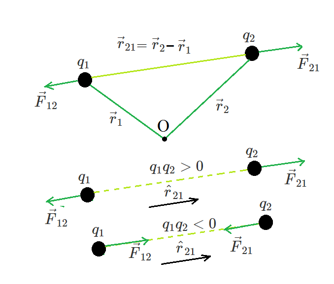
Coulomb’s law is better written in vector notation because force is a vector quantity. Charges q1 and q2 have location vectors r1 and r2, respectively. F12 denotes force on q1 owing to q2 and F21 denotes force on q2 owing to q1. For convenience, the two-point charges q1 and q2 have been numbered 1 and 2, respectively, and the vector leading from 1 to 2 has been designated by r21.
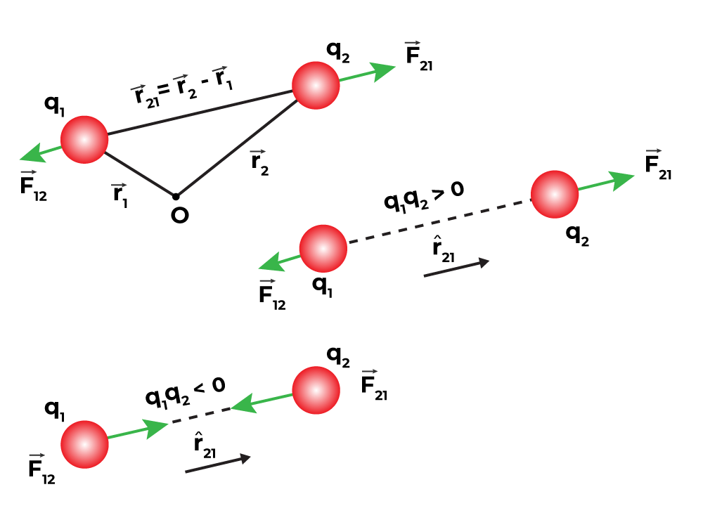
Similarly, the vector leading from 2 to 1 is denoted by r12,
r21 and r12 are the magnitudes of the vectors and , respectively and magnitude r12 is equal to r21. A unit vector along the vector specifies the vector’s direction. The unit vectors are used to denote the direction from 1 to 2 (or 2 to 1). The unit vectors define as,
Similarly,
Coulomb’s force law between two point charges q1 and q2 located at vector r1 and r2 is then expressed as,
Key Points on Coulomb’s Law
- Coulomb’s Law holds true regardless of whether q1 and q2 are positive or negative. F21 is toward , which is a repulsive force, as it should be for like charges that are if q1 and q2 are of the same sign (either both positive or both negative). When the signs of q1 and q2 are opposite or dislike charges, F21 is toward , that is toward which shows attraction, as expected for dissimilar charges. As a result, we don’t need to construct separate equations for like and unlike charges. Both instances are handled correctly by the above expression for Coulomb’s force law.
- Coulomb’s force law can be used to calculate the force F12 on charge q1 due to charge q2 by simply swapping 1 and 2 as,
- Coulomb’s law agrees with Newton’s third law.
- In a vacuum, Coulomb’s law expression determines the force between two charges q1 and q2. If the charges are deposited in matter or there is matter in the intervening area, the situation becomes more complicated due to the presence of charged matter constituents.
- Two identical conductors with charges q1 and q2 are brought into contact and subsequently separated, resulting in each conductor having a charge equal to (q1+q2)/2. Each charge will be equal to (q1-q2)/2 if the charges are q1 and –q2.
What is 1 Coulomb of Charge?
Columb is the SI unit of charge. If a charge repels an equal charge of the same sign with a force of 9×10⁹ N the charge is of 1 Coulomb given so the charges are one meter apart in a vacuum.
1 coulomb is a bigger unit of charge and is not used in daily life. We use smaller units such as micro coulomb, etc.
Conditions for Stability of Coulomb’s Law
If two charges are arranged in a straight line AB and one charge q is slightly displaced towards A, the force acting on A FA increases in magnitude while the force acting on B FB decreases in magnitude. Thus, the net force on q shifts towards A. So we can say that for axial displacement, the equilibrium is unstable.
If q is displaced perpendicular to line AB, the force FA and FB are changed in such a manner that they bring the charge to its original position. Now we can say that for perpendicular displacement, the equilibrium is stable.
Applications of Coulomb’s Law
Coulomb’s Law is one of the basic laws of Physics. It is used for various purposes, some of its important applications are discussed below,
- It is used to calculate the distance and force between the two charges.
- It is used to arrange the charges in stable equilibrium.
- Columbus law is used to calculate electric field.
An electric field is given by,
E = F / QT (N/C)
where,
- E is the Strength of the electric field
- F is the Electrostatic force
- QT is the Test charge measured in coulombs
Limitations of Coulomb’s Law
There are some limitations of Coulomb’s Law which are discussed below in the article,
- Coulomb’s Law is applicable for the point charges which are at rest.
- Coulomb’s Law is only applicable in situations where the inverse square law is followed.
- Coulomb’s Law is applicable only for the charges which are considered to be spherical. For charges with arbitrary shapes, Coulomb’s Law is not applicable because we cannot determine the distance between the charges.
Also, Check
Solved Example on Coulomb’s Law
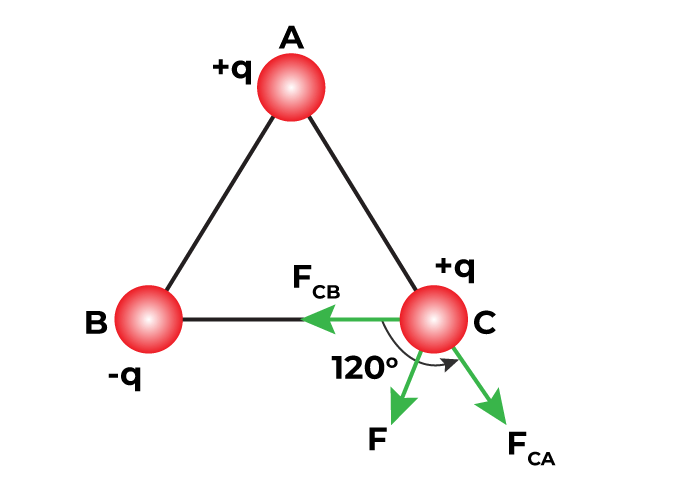
Example 1: Charges of magnitude 100 micro coulombs each are located in a vacuum at the corners A, B and C of an equilateral triangle measuring 4 meters on each side. If the charge at A and C are positive and the charge at B negative, what is the magnitude and direction of the total force on the charge at C?
Solution:
Force FCA is applied toward AC and the expression for the FCA is expressed as
Substitute the values in the above expression,
The Force FCB is applied toward CB and the expression for the FCB is expressed as
Substitute the values in the above expression,
Therefore, the two forces are equal in magnitude but in different directions. The angle between them is 120º. The resultant force F is given by,
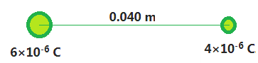
Example 2: A positive charge of 6×10⁻⁶ C is 0.040 m from the second positive charge of 4×10⁻⁶ C. Calculate the force between the charges.
Solution:
Given,
First charge q1 = 6×10⁻⁶ C.
Second charge q2 = 4×10⁻⁶ C.
Distance between the charges r = 0.040 m
k = 9×10⁹
We know that, F = k q1q2 / r2
Substitute the values in the above expression,
F = k q1q2 / r2
F = 9×10⁹×[(6×10-6)× (4×10-6)] / (0.04)2
F= 134.85 N
Example 3: Two-point charges, q1 = +9 μC and q2 = 4 μC are separated by a distance r = 12 cm. What is the magnitude of the electric force?
Solution:
Given,
- k = 8.988 x 10⁹ Nm2C−2
- q1 = +9μC = 9 × 10⁻⁶ C
- q2 = +4μC = 4 × 10⁻⁶C
- r = 12cm = 0.12m
F = k (q1q2 ∕ r2)
F = (8.9875 × 10⁹ ) [(9x 10⁻⁶ ) × (4 x 10⁻⁶) / (0.12)2]
F = (8.9875 × 10⁹ ) [36 × 10-12 /0.0144]
F = 22470 N
Electric force between the charges is approximately 22.47 N
For more Problems on Coulomb’s Law
FAQs on Coulomb’s Law
Define Coulomb’s Law.
The electrostatic force of attraction or repulsion between two stationary point charges is directly proportional to the product of the magnitudes of the charges and inversely proportional to the square of the distance between them i.e.
F ∝ q1q2 / r2
State Coulomb’s Inverse-square Law in Electrostatics.
Coulomb’s Inverse-square law in electrostatics states that the force applied between two electrically charged particles is inversely proportional to the square of the distance between two particles.
What is One Coulomb of Charge?
If one ampere of current passes through a conductor in one second then the charge transfer is one coulomb. One coulomb charge is also defined as the charge carried by 6×10¹⁸ electrons.
Is Electrostatic Force between any two point charges a central force?
Yes. The electrostatic force between two point charges always acts along the line joining the two charges. Hence it is a central force.
What are Conditions for Stability of Coulomb’s Law?
Condition for stability of Coulomb’s Law is if a charge is introduced in a stable system of n charges then it is placed in such a position that the force on the test charge through all the other charges must cancel out each other.
List some of the Application Of Coulomb’s Law.
Coulomb’s law is one of the fundamental laws of electrostatics and some applications of Coulomb’s Law are,
- It provides the force between electric charges.
- It is used to arrange electric charges in stable conditions.
- It is used to calculate the distance between two charges.
- It is used to tell the force acting at a point due to various charges.
Electric Dipole
Electric Dipole
Electric Dipole
An electric dipole is defined as a pair of equal and opposite electric charges that are separated, by a small distance. An example of an electric dipole includes two atoms separated by small distances. The magnitude of the electric dipole is obtained by taking the product of either of the charge and the distance between them. In this article, we will learn about electric dipole its application, and others in detail.
Table of Content
- What is Electric Dipole?
- Visualising Electric Dipole
- Magnitude and Dimension of an Electric Dipole
- Direction of Electric Dipole Moment
- Electric Potential due to a Dipole (V)
- Electric Field of an Electric Dipole
- Dipole in an External Electric Field
- Physical Significance of Dipoles
- Solved Examples on Electric Dipole
What is Electric Dipole?
A pair of equal and opposite point charges q and –q separated by a distance 2a form an electric dipole and the electric dipole moment (p) is the product of the charge and the space between the charges (2a). It is used to determine the strength of an electric dipole.
.png)
As we know that Electric Dipole is a vector quantity i.e. it has both magnitude and direction. The magnitude of the electric dipole is the product of either of the electric charge and the distance between them. The direction of the electric dipole is from negative charge to positive charge.
Visualising Electric Dipole
Let’s take two charges +q and -q equal in magnitude but opposite in direction, and the distance between them is d. Then this system is called the electric dipole.
An electric dipole is denoted by the symbol “p”. It is a Vector quantity. In the image given below two point charges +q and -q are separated by distance ‘d’ and hence the electric dipole moment is p = q×d
Magnitude and Dimension of an Electric Dipole
An electric dipole is a vector quantity and its magnitude is given as,
|p| = q×d
It is clear that the magnitude of the electric dipole is the product of either charge with the distance between them.
Electric Dipole is measured in Coulomb-meter. Its dimensional formula is [M0 L1 T1 I1]
Direction of Electric Dipole Moment
Electric dipole moment is a vector quantity and hence it has a unique direction. The direction of the electric dipole is from negative charge to positive charge. The Axis of the electric dipole moment is the line that joins both charges.
Note: It is important to note that the direction of Electric Dipole Moment is taken from negative end to positive end in physics. In Chemistry, the direction of Electric Dipole Moment is taken to be opposite i.e. from positive charge to negative charge.
Electric Potential due to a Dipole (V)
Let’s take two charges -q and +q placed at A and B respectively. The distance between them AB is d they form a dipole as p = qd the centre of AB is Q. Now, if any point P which makes an angle θ with the AB and QP is r then the electric potential at P by the electric dipole is given by,
V = 1 / 4πεo × [p cos(θ) / r2]
When θ = 0°
Then,
cos θ = cos 0° = 1
Now,
V = 1 / 4πεo × [p cos(θ) / r2]
V = 1 / 4πεo × [p cos(0°) / r2]
V = 1 / 4πεo × [p / r2]
When θ = 90°
Then,
cos θ = cos 90° = 0
Now,
V = 1 / 4πεo × [p cos(θ) / r2]
V = 1 / 4πεo × [p cos(90°) / r2]
V = 0
Also Check:
Electric Field of an Electric Dipole
Coulomb’s law and the superposition principle may be used to calculate the electric field of a pair of charges (–q and q) at any point in space. For the following two scenarios, the results are simple and clear,
- When the point is on the dipole axis,
- When it is on the equatorial plane of the dipole, i.e. on a plane perpendicular to the dipole axis through its centre.
By applying the parallelogram law of vectors, the electric field at any general point P is determined by summing the electric fields E–q due to the charge –q and E+q due to the charge q.
For Points on Axis
.png)
Suppose the point P be at distance r from the centre of the dipole on the side of the charge q. Then electric field E–q due to the charge –q can be expressed as,
where
is the unit vector along the dipole axis that is from –q to q.
Similarly, Then electric field E+q due to the charge +q can be expressed as,
Now, the total field at P can be calculated by adding the electric fields E–q due to the charge –q and E+q due to the charge +q and can be expressed as,
For r >> a the above expression can be written as,
For Points on Equatorial Plane
.png)
Then, the electric field E+q due to the charge +q can be expressed as,
Similarly, then the electric field E-q due to the charge –q can be expressed as,
It is observed that the electric fields E–q due to the charge –q and E+q due to the charge +q are equal. The E+q and E–q directions are displayed in the above-given figure. The components normal to the dipole axis clearly cancel out. Along the dipole axis, the components add up. The entire electric field is in the opposite direction of .
The above expression can be added as,
At large distances (r >> a), the above expression can be written as,
At great distances, it is evident in both cases that the dipole field does not involve q and a separately; it is dependent on the product qa. This hints at the meaning of the dipole moment. The dipole moment of an electric dipole is a vector quantity and it is symbol is p is defined by
The electric field of a dipole at large distances (r >> a) assumes simple shapes in terms of p:
- At a point on the dipole axis:
- At a point on the equatorial plane:
It’s worth noting that the dipole field at great distances decreases off as 1/r3 rather than 1/r2. Furthermore, the dipole field’s amplitude and direction are dependent not only on the distance r but also on the angle formed by the position vector r and the dipole moment p.
Dipole in an External Electric Field
The image given below shows an electric dipole kept in an electric field and torque applied to it.
.png)
Suppose a permanent dipole in a uniform external field E with a dipole moment of p. On q, there is a force qE and on –q, there is a force –qE. Because E is uniform, the net force on the dipole is zero. Due to the separation of the charges, the forces operate at various places, causing a torque on the dipole. The torque (couple) is independent of the origin when the net force is zero. Its amplitude is equal to the sum of the magnitudes of the two antiparallel forces multiplied by the couple’s arm (perpendicular distance between the two antiparallel forces). The magnitude of torque can be expressed as,
τ = q E × 2 a sinθ
τ = 2 q an E sinθ
Its direction is perpendicular to the plane of the paper, coming out of it. The magnitude of p × E is also pE sinθ and its direction is normal to the paper, coming out of it.
τ = = p × E
The dipole will tend to align with field E as a result of this torque. The torque is 0 when p is aligned with E.
If the field is not uniform, the net force will undoubtedly be greater than zero. Additionally, like before, there will be torque on the system. Because the general case is complicated, consider the simpler cases when p is parallel to E or antiparallel to E. The net torque is zero in both cases, but there is a net force on the dipole if E is not uniform.
For more detail click, Torque on an Electric Dipole in Uniform Electric Field
Physical Significance of Dipoles
With the help of electric dipole moment, we can easily determine the geometry and orientation of any compound in 3-D space.
Everything around us is made up of molecules and molecules can easily be categorized into two categories.
- Polar Molecules
- Non-Polar Molecules
Polar Molecules: The molecules which have a net dipole movement are called polar molecules. e.g. HCl. NaOH, etc. In an external electric field polar molecules align themselves in the direction of the electric field.
Non-Polar Molecules: The molecules in which individual dipole moments cancel out each other are called Non-polar molecules. i.e. in a Non-Polar molecule, the net dipole moment is Zero. e.g. CO2, O2,, etc.
Read More
Solved Examples on Electric Dipole
Example 1: Given a uniform electric field, find the flux of this field through a square of side 20 cm, whose plane is parallel to the y-z plane. What would be the flux through the same square, if the plane makes an angle of 30° with the x-axis?
Solution:
Given,
Electric field is
A = 10 × 10 × 10-4m2,
Flux (ϕ) = EA cos θ
Case 1,
θ = 0°,
or cos 0° = 1
Therefore, Flux, ϕ= (5 × 103) × (10 × 10 × 10-4) cos 0°
ϕ = 50 Nm2C-1
Case 2,
Angle of square plane with x-axis = 30°
Hence, the angle will be (90° – 30°) = 60°
ϕ = EA cos θ
ϕ = (5 × 103) × (10 × 10 × 10-4) × cos 60°
ϕ = 50 × 1/2
ϕ = 25 Nm2C-1
Example 2: Define the term ‘electric flux’. Write its S.I. units. What is the flux due to the electric field through a square of side 10 cm, when it is held normally too if?
Solution:
The total number of lines of force moving through an area in an electric field is known as electric flux. It’s represented by the symbol ϕ. It’s a number with a scalar value. Its S.I unit is Nm2 C-1 or Vm.
It is expressed as,
Given,
Electric field is 3×10³ N/C.
Area is (10/100)×(10/100) m2 = 10-2 m2
θ = 0°,
or
cos 0° = 1
The expression for the flux can be written as,
ϕ = EA cos θ
Therefore, Flux, ϕ= (3 × 103) × (10-2) cos 0°
ϕ = 30 Nm2C-1
Electic Dipole – FAQs
What is the force acting on a dipole placed in a uniform electric field?
The net force acting on the electric dipole is zero, as the dipole consists of two opposite charges that apply force in opposite directions.
What is the SI unit of the dipole moment?
The dipole moment is measured in Coulomb-metre. It is also the SI of dipole movement.
Give an example of the electric dipole.
An example of an electric dipole is pair of electric charges of opposite signs and equal magnitude separated by a small distance.
What is the Direction of an Electric Dipole Moment?
As we know that electric dipole moment is a vector quantity so it has both magnitude and direction and its direction is always considered from the negative charge to the positive charge.
When is the torque maximum on a dipole?
If the dipole is kept perpendicular to the electric field, then the torque generated is maximum.
When is the torque minimum on a dipole?
If the dipole is kept parallel to the electric field, then the torque generated is minimum.
Why do the electric field lines not form closed loops?
Because the direction of an electric field is from positive to negative charge, it does not form closed loops. As a result, a line of force can be seen as starting with a positive charge and terminating with a negative charge.
Dipole Moment
Two small charges (equal and opposite in nature) when placed at small distances behave as a system and are called as Electric Dipole. Now, electric dipole movement is defined as the product of either charge with the distance between them. Electric dipole movement is helpful in determining the symmetry and 3-D orientation of any polar molecule. In this article, we will learn about the Dipole movement, its properties, Formula, and others in detail.
What is Dipole Moment?
A pair of equal and opposite point charges q and –q separated by a distance 2a form an electric dipole and the electric dipole moment (p) is the product of the charge and the space between the charges (2a), is used to determine the strength of an electric dipole.
A direction in space is defined by the line joining the two charges. The direction from –q to q is commonly referred to as the dipole’s direction. The centre of the dipole is the location of the middle point of –q and q.
The electric dipole’s overall charge is zero. This does not imply that the electric dipole’s field is zero. Because the charges q and –q are separated by a certain distance, the electric fields produced by them do not exactly cancel out when put together. The fields attributable to q and –q almost cancel out over distances much greater than the spacing of the two charges producing a dipole (r >> 2a).
Dipole Moment Formula
Dipole moment is represented by the Greek letter ‘µ’ and is defined as the product of the magnitude of either charge and the distance between them, the formula for the calculation of dipole moment is,
Dipole Moment (µ) = Charge (Q) × distance of separation (r)
μ = δ.d
where,
μ is the bond dipole moment
δ is the magnitude of the partial charges δ+ and δ–
d is the distance between charges
Unit and Dimensions of Dipole Moment
Dipole Moment is measured in Debye denoted by ‘D’.
1 D = 3.33564 × 10⁻³⁰ C.m
where
C is Coulomb
m denotes a metre
Its dimensional formula is [M0L1T1I1].
Dipole Moment (μ) is a vector quantity, whose direction is measured from +q to -q charge.
The image given below shows the dipole moment of the HCl molecule.
.png)
Dipole Moment of BeF2
The net Dipole Moment of the BeF2 Beryllium Fluoride molecule is zero. The bond angle between the BeF2 molecule is 180°, and the two dipole moments are opposite to each other and they cancel out each other. The image given below shows the dipole moment of the BeF2.
.png)
Dipole Moment of H2O (Water)
The net Dipole Moment of the H2O water molecule is found to be 1.84 D. The bond angle in the water molecule is 104.5°, the water molecule has two oxygen-hydrogen bonds that can individually be treated as dipole and their individual bond moment of an oxygen-hydrogen bond is 1.5 D. The image given below shows the dipole moment of the H2O.
.png)
Dipoles in an External Electric Field
If an electric dipole is placed in an external electric field the electric dipole experiences some force called torque. It is represented by the Greek letter τ. The torque in any external electric field on the dipoles is given by,
τ = P x E
= PE Sin θwhere,
P is the Dipole Moment
E is the Applied External Field
Significance of Electric Dipole Moment
Electric Dipoles are not only studied in Physics but are also very important in Chemistry. The significance of Electric Dipole is by categorizing molecules.
Molecules on the basis of electric dipole moment are divided into two categories,
- Polar Molecules: If any molecule has a net dipole moment then it is called a polar molecule. For example, HCl is a polar molecule. These molecules are randomly arranged in the absence of an external electric field. On applying an electric field, the polar molecules align themselves according to the direction of the electric field.
- Non-Polar Molecules: If any molecule has a net dipole moment of zero then it is called a non-polar molecule. For example, BeF2 is a non-polar molecule.
Uses of Dipole Moment
Every compound is made up of bonds and bonds have polarity. The polar nature of any bond is studied using the Dipole movement of that compound. Molecules with high dipole movement have high polarity and molecules with no dipole movements are non-polar in nature. The various uses of dipole movements are,
- Dipole moment tells us about the symmetry of the molecules. i.e. molecules with high dipole movement are generally non-linear and asymmetrical, whereas molecules which have zero dipole movement are symmetrical and linear.
- Cis- and Trans-isomers of any compound can easily be distinguished using the dipole moment. Compounds with high dipole moment are generally trans-isomers and compounds with low dipole moment are cis-isomers.
- Dipole movement helps us to find the percentage ionic character of a molecule.
- Ortho, Para and Meta compounds are also distinguished using the dipole moment.
Read, More
FAQs on Dipole Moment
Question 1: What is a Dipole Moment?
Answer:
The product of charge on either end of the dipole with the distance between them is called the Dipole moment.
Question 2: What is the SI unit of the Dipole Moment?
Answer:
SI unit of the Dipole Moment is Coulomb-metre.
Question 3: Where is Dipole Moments used?
Answer:
There are various uses of Dipole Moment some of them are,
- They are used to determine symmetry in a molecule.
- They explain the various physical properties of the compounds, etc.
Question 4: When is the torque on a Dipole maximum?
Answer:
The torque on the dipole is maximum if the dipole is placed perpendicular to the electric field.
Question 5: When is the torque on a Dipole minimum?
Answer:
The torque on the dipole is minimum if the dipole is placed parallel to the electric field.
Question 6: How do you find the dipole moment of CO2?
Answer:
CO2 has a linear structure, it has two dipole moments which cancel out each other and hence the net dipole moment of CO2 is zero.
Forces Between Multiple Charges
When our synthetic clothing or sweater is removed from our bodies, especially in dry weather, a spark or crackling sound appears. With females’ clothing like a polyester saree, this is almost unavoidable. Lightning, in the sky during thunderstorms, is another case of electric discharge. It is an electric shock always felt while opening a car door or grabbing the iron bar of a bus after sliding out of our seats. The cause of these sensations is the discharge of electric charges that have collected as a result of rubbing insulating surfaces. This is due to static electricity generation. Anything that does not have movement or change with time is referred to as static. The study of forces, fields, and potentials coming from static charges is known as electrostatics.
Coulomb’s Law
Coulomb’s law is a mathematical formula that describes the force between two point charges. When the size of charged bodies is substantially smaller than the separation between them, then the size is not considered or can be ignored. The charged bodies can be considered as point charges. Coulomb studied the force between two point charges and found that it is inversely proportional to the square of the distance between them, directly proportional to the product of their magnitudes, and acting in a line that connects them.
Expression for Coulomb’s Law
The amount of the force (F) between two point charges q1 and q2 separated by a distance r in a vacuum is given by

Where F is the force between two point charges, q1 and q2 are the point charge, r is the distance between the point charge and k is proportionality constant. For subsequent simplicity, the constant k in the above expression is commonly written as

Here,  is known as the permittivity of free space. The value of in SI units is

Coulomb’s Law in Vector Form
Geometry and Forces between charges
Coulomb’s law is better written in vector notation because force is a vector quantity. Charges q1 and q2 have location vectors r1 and r2, respectively. F12 denotes force on q1 owing to q2 and F21 denotes force on q2 owing to q1. For convenience, the two-point charges q1 and q2 have been numbered 1 and 2, respectively, and the vector leading from 1 to 2 has been designated by r21.

Similarly, the vector leading from 2 to 1 is denoted by r12,

r21 and r12 are the magnitudes of the vectors  and
and  , respectively and magnitude r12 is equal to r21. A unit vector along the vector specifies the vector’s direction. The unit vectors are used to denote the direction from 1 to 2 (or 2 to 1). The unit vectors define as,

Similarly,

Coulomb’s force law between two point charges q1 and q2 located at vector r1 and r2 is then expressed as

Force Between Multiple Charges
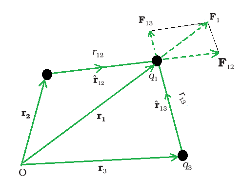
A system of three charges.
Consider a system in a vacuum with n motionless that is stationary charges q1, q2, and q3. It has been proven experimentally that the vector sum of all the forces on a charge due to a number of other charges, taken one at a time, is the vector sum of all the forces on that charge owing to the other charges. Due to the presence of other charges, the separate forces remain unaffected. This is known as the superposition principle.
The force on one charge, say q1, due to two other charges, q2 and q3, may be determined by conducting a vector addition of the forces due to each of these charges. As a result, if F12 denotes the force exerted on q1 as a result of q2,

Similarly, F13 denotes the force exerted on q1 as a result of q3, which again is the Coulomb force on q1 due to q3 even though other charge q2 is present. Thus, the total force F1 on q1 due to the two charges q2 and q3 can be expressed as,
![\overrightarrow{F}_{1}=\overrightarrow{F}_{12}+\overrightarrow{F}_{13}\\ \overrightarrow{F}_{1}=\frac{1}{4\pi{\epsilon}_\circ}\frac{q_1q_2}{{r}_{12}^2}\hat{r}_{12}+\frac{1}{4\pi{\epsilon}_\circ}\frac{q_1q_3}{{r}_{13}^2}\hat{r}_{13}\\ \overrightarrow{F}_{1}=\frac{q_1}{4\pi{\epsilon}_\circ}\left[\frac{q_2}{{r}_{12}^2}\hat{r}_{12}+\frac{q_3}{{r}_{13}^2}\hat{r}_{13}\right]](https://www.geeksforgeeks.org/wp-content/ql-cache/quicklatex.com-f5877d351151aa9fe715e707ceead2c7_l3.svg "Rendered by QuickLaTeX.com")
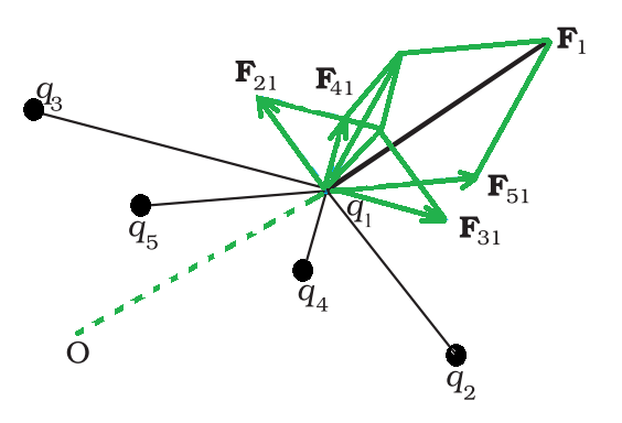
A system of multiple charges.
The above force calculation can be applied to a system with more than three charges. The principle of superposition states that in a system of charges q1, q2…….qn, the force on q1 owing to q2 is the same as Coulomb’s law, i.e., it is unaffected by the presence of other charges q3, q4,…, qn. The vector sum of the forces F12, F13,…, F1n on the charge q1 owing to all other charges gives the overall force F1 can be written as
![\overrightarrow{F}_{1}=\overrightarrow{F}_{12}+\overrightarrow{F}_{13}+....+\overrightarrow{F}_{1n}\\ \overrightarrow{F}_{1}=\frac{q_1}{4\pi{\epsilon}_\circ}\left[\frac{q_2}{{r}_{12}^2}\hat{r}_{12}+\frac{q_3}{{r}_{13}^2}\hat{r}_{13}+....+\frac{q_n}{{r}_{1n}^2}\hat{r}_{1n}\right]\\ \overrightarrow{F}_{1}=\frac{q_1}{4\pi{\epsilon}_\circ}\sum_{i=2}^n\frac{q_i}{{r}_{1i}^2}\hat{r}_{1i}](https://www.geeksforgeeks.org/wp-content/ql-cache/quicklatex.com-789a16842a10915a58c9f548e2824c5c_l3.svg "Rendered by QuickLaTeX.com")
The vector sum is calculated by using the parallelogram law of vector addition. Coulomb’s law and the superposition principle are the foundations of electrostatics.
Key Points on Coulomb’s Law
- The above expression holds true regardless of whether q1 and q2 are positive or negative. F21 is toward
 , which repulsive force, as it should be for like charges that are if q1 and q2 are of the same sign (either both positive or both negative). When the signs of q1 and q2 are opposite or dislike charge, F21 is toward
  , that is toward
  which shows attraction, as expected for dissimilar charges. As a result, we don’t need to construct separate equations for like and unlike charges. Both instances are handled correctly by the above expression for Coulomb’s force law.
 - The above expression for Coulomb’s force law can be used to calculate the force F12 on charge q1 due to charge q2 by simply swapping 1 and 2 as,

Coulomb’s law therefore agrees with Newton’s third law.
- In a vacuum, Coulomb’s law expression determines the force between two charges q1 and q2. If the charges are deposited in matter or there is matter in the intervening area, the situation becomes more complicated due to the presence of charged matter constituents.
- Two identical conductors with charges q1 and q2 are brought into contact and subsequently separated, resulting in each conductor having a charge equal to (q1+q2)/2. Each charge will be equal to (q1-q2)/2 if the charges are q1 and –q2.
Electric Charge
The word “electricity” comes from the Greek word “electron,” which means “amber”. The magnetic and electric forces present in materials, atoms, and molecules affect their properties. The term “electric charge” refers to just two types of entities. According to the results of an experiment, there are two types of electrification:
- Like charges repel one another and
- Unlike charges attract each other
The polarity of charge is the feature that distinguishes these two types of charges.
Conductors and Insulators
When an experiment on electric charges caused by frictional electricity was carried out, it was discovered that conductors aid in the flow of electric charge, whereas insulators do not. Metal, Earth, and Human Bodies are all conductors, but porcelain, nylon, and wood are all insulators, offering high resistance to the flow of electricity through them.
Properties of Electric charge
There are three basic qualities of an electric charge:
- Quantization: The total charge of a body indicates the integral multiple of a basic quantum of charge.
- Additive: This electric charge property reflects a body’s overall charge as the algebraic sum of all singular charges acting on the system.
- Conservation: The entire charge of a system remains unchanged throughout time, according to conservation. In other words, when objects become charged as a result of friction, the charge is transferred from one object to another. There is no way to create or eliminate charges.
Properties of Electric Field Lines
The following are some of the general characteristics of field lines:
- In a charge-free zone, field lines show a continuous curve with no breaks.
- Electric Field Lines never cross each other.
- These electric field lines begin with a positive charge and conclude with a negative charge.
- Electrostatic field lines do not form any closed loops.
Sample Problems
Problem 1: A positive charge of 6×10⁻⁶ C is 0.040 m from the second positive charge of 4×10⁻⁶ C. Calculate the force between the charges.
Solution:
Given,
A positive charge q1 is 6×10⁻⁶ C.
The second positive charge q2 is 4×10⁻⁶ C.
The distance between the charges r is 0.040 m.
Substitute the values in the above expression,


Problem 2: Four equal charges q are kept on corners of a square of the side ‘r’, find the net force on one of the charges.
Solution:
Given,
Four equal charges ‘q’ and the distance between them is r.
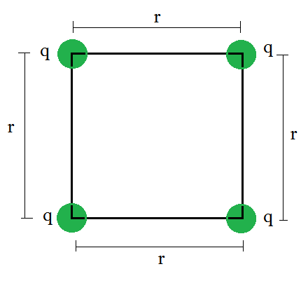
The individual repulsive forces on the corner charge q and make a vector diagram and note down the forces, which as:
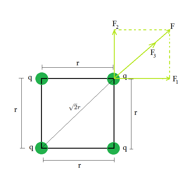
The force due to the Left top charge on the right top charge is F1 and can be expressed as,
F1 = (kq2)/r2
The force due to the right bottom charge on the right top charge is F2 and can be expressed as,
F2 = (kq2)/r2
The force due to the Left bottom charge on the right top charge is F3 and can be expressed as,

The resultant force on the right top charge can be written as,
Here cos 90o is equal to 0.
Substitute the value in the above expression.


Problem 3: Charges of magnitude 100 microcoulomb each are located in vacuum at the corners A, B, and C of an equilateral triangle measuring 4 meters on each side. If the charge at A and C are positive and the charge B negative, what is the magnitude and direction of the total force on the charge at C?
Solution:
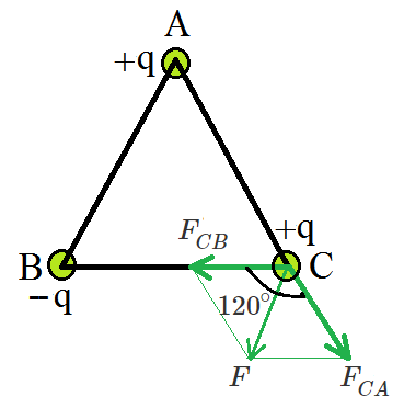
The Force FCA is applied toward AC and the expression for the FCA is expressed as
Substitute the values in the above expression,
The Force FCB is applied toward CB and the expression for the FCB is expressed as
Substitute the values in the above expression,
Therefore, the two forces are equal in magnitude but in different directions. The angle between them is 120º. The resultant force F is given by,


Problem 4: Compare the nature of electrostatic and gravitational forces.
Solution:
Between two huge masses, a gravitational force acts. However, an electrostatic force is activated when two charged bodies come into contact.
Similarities:
- These two forces are central forces.
- Follow the law of inverse squares.
- They’re both long-range forces.
- Both forces are naturally conservative.
Dissimilarities:
- In nature, electrostatic force can be both attractive and repellent. In nature, gravitational force can only be attractive.
- The material medium between two charges affects the electric force between them. The material medium between huge bodies has little effect on gravitational force.
- Electric forces are extremely powerful approximately 10 38 times stronger) than gravitational forces.
Problem 5: Why does Coulomb’s force act between two charges only in the line joining their centers?
Solution:
Because of the fundamental features of electrical charge, this is the case. Charges that are similar repel each other. Charges that are diametrically opposed attract each other.
The force of attraction or repulsion between two charges will be directed in the direction so that the force does the least amount of work. As a result of this requirement, the action is directed along the straight line connecting the two charges, which is the shortest distance between them.
Electric Field
Electric field is a fundamental concept in physics, defining the influence that electric charges exert on their surroundings. This field has both direction and magnitude. It guides the movement of charged entities, impacting everything from the spark of static electricity to the functionality of electronic devices Understanding electric fields will help you to understand how charge particles interact with each other and the surroundings and guide various natural and technological phenomena. In this article, we will learn in detail about electric field, its formula, calculation of electric field for ring, straight wire and continuous charge distribution.
Table of Content
What is an Electric Field?
Electric Field is a fundamental concept in physics, they are a physical field that surrounds an electrically charged particle. Charged particles exert attractive force when they have opposite charges and repulsive force when they have the same charges in this field. The electric field of a single charge describes its power to exert such forces on another charged object.
The electric field is a vector quantity which means it has both magnitude and direction.
Electric Field Formula
Mathematically electric field(E) is described at a given point is defined as the force (F) experienced by a test charge (q) placed at that point, divided by the magnitude of the test charge:
E = F/q
Direction Of Electric Field
The direction of electric field is taken as the direction of the force which is exerted on the positive charge. The electric field is radially outwards from the positive charge and radially inwards to the negative point charge, as shown in the picture given below:
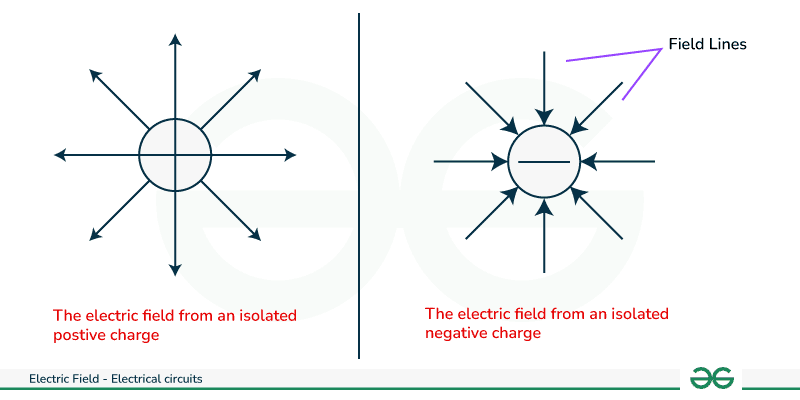
Key Terminologies Related to Electric Field
Now, let us see some of the important terminologies related to electric field that will be discussed further in the article:
- Electric Charge: An electric charge is a property of matter that causes two objects to repel or attract. It can be either negative or positive.
- Point charge: When discussing a body considerably smaller than the distance being considered, we disregard its size and refer to it as a point charge.
- Coulomb's Law: Coulomb's law states that the force between two point charges is directly proportional to the magnitudes of the charges and inversely proportional to the distance between the two charges.
- Mathematically : F = (k|q1q2|)/r2 ,where q1=first point charge ,q2 = second point charge.
- k = 8.988 * 109 Nm2/C2 is Coulomb’s constant, r = the distance between two point charges.
- Gauss's law : Gauss’s law states that the net flux of an electric field in a closed surface is directly proportional to the enclosed electric charge.( further discussed in detail in the article).
- Electric flux: Electric flux is defined as the total number of electric field lines passing through a specified area within a unit of time.
Electric Field Lines
Electric field lines are imaginary lines used to depict the direction and strength of an electric field surrounding charged objects. They were introduced by the physicist Michael Faraday in the 19th century as a conceptual tool for understanding electric fields.
Properties of Electric Field Lines
Electric field lines have different properties. Some of the properties are provided below:
- Field lines never intersect each other.
- They are perpendicular to the surface charge.
- The strength of an electric field increases when the field lines are closer together, which indicates a stronger force. Conversely, when field lines move farther apart, the field weakens.
- The quantity of field lines directly proportional to the magnitude of the charge.
- These lines generally originate from positive charges and ends at negative charges, depicting the direction of the electric field.
Electric Field Calculation
Various methods are followed to calculate electric field are as followed:
Calculate Electric Field Using Coulomb's Law
According to Coulomb's law, a force with electric charge q1 at position x1 exerts a force on a particle with charge q2 at position x0 of ,(equation-1)
where
is a unit vector in the direction from of electrostatic force - ε0 is the electric constant, known as absolute permittivity of free space .
We know that electric field is given as force per unit test charge. Let q is the test charge. Hence, electric field is given as
Calculate Electric Field Using Gauss's Law
Gauss's law states that the total flux linked with a closed surface is 1/ε0 times the charge enclosed by the closed surface. Hence, according to Gauss Law, electric field is given as follows:
It is easy to calculate electric field using Gauss's law as compare to Coulomb's law. If we carefully observe, Gauss's law is a replica of Coulomb's law.
How to Find the Electric Field Using Gauss Law?
- Choose a Symmetrical Gaussian Surface: Select a closed surface where the electric field is constant in magnitude and direction. The symmetry can be spherical, cylindrical or planar depending upon the charge distribution.
- Determine the Enclosed Charge: Calculate the total charge enclosed in the chosen Gaussian surface.
- Calculate Electric Flux: Evaluate the flux of the electric field through the Gaussian surface
- Ultimately leads to finding the electric field using gauss law with the help of the formula given above.
Let's say you have a spherically symmetric charge distribution with total charge Q uniformly distributed within a sphere of radius R. Our aim is to find electric field at a distance r from the center:
- Choose a Gaussian Surface: A spherical Gaussian surface with radius r > R is suitable for this case.
- Determine Enclosed Charge: The enclosed charge is q for r ≤ R and Q for r > R (as whole body is enclosed).
- Calculate Electric Flux: The electric flux through the spherical surface is given as E × A, where E is the magnitude of the electric field and A is area
- Apply Gauss's Law: By Set up Gauss's law equation:
From Gauss Law
4πr2.E = Q/ε0
From this equation, you can solve for the magnitude of the electric field
E at a distance r from the center is given as
This example illustrate how to use Gauss's law for a spherically symmetric charge distribution. See, the approach and the shape of the Gaussian surface can vary based on the symmetry of the charge distribution provided in the question.
Electric Field For Continuous Charge Distribution
Let us talk about the different types of charge distribution
- Linear Charge Distribution
- Surface Charge Distribution
- Volume Charge Distribution
Linear Charge Distribution
Linear charge distribution: If charge is distributed linearly over a body.
λ = dq/dl
- λ = linear charge density
- dq = charge
- dl = line element
Consider an infinitesimally small element of charge (dq) along the line, the electric field contribution (dE) from this element can be calculated using Coulomb's law: dE = k⋅dq/r2 where k is Coulomb's constant.
Integrate dE over the entire length of the line charge to obtain the total electric field E = ∫k⋅dq/r2
Surface Charge Distribution
Surface charge distribution: If charge is distributed continuously over the surface of a body
σ = dq/ds
- σ = surface charge density
- dq = charge
- ds = surface element
Consider an infinitesimally small element of charge (dq) on the surface, the electric field contribution (dE) from this element can be calculated using Coulomb's law: dE = k⋅dq/r2, where k is Coulomb's constant.
Integrate dE over the entire surface to obtain the total electric field E = ∫k⋅dq/r2
Volume Charge Distribution
Volume charge distribution: If charge is distributed continuously over the volume of a body.
ρ = dq/dv
- ρ = volume charge density
- dq = charge
- dv = volume element
Consider an infinitesimally small volume element containing charge (dV) within the region, the electric field contribution (dE) from this volume element can be calculated using Coulomb's law: dE = k⋅dq/r2, where dq = ρ⋅dV and k is Coulomb's constant.
Integrate dE over the entire volume to obtain the total electric field E = ∫k⋅dq/r2
Applications of Gauss Law to Find Electric Field
Now, let us see some of the application of gauss law to find electric field:
Electric Field due to a Line Charge
Suppose a line charge having linear charge density λ is given in the form of a thin charged rod.
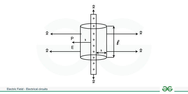
To find the electric field intensity at point P along a wire, a cylindrical Gaussian surface is selected. This choice is made to apply Gauss's law for finding the electric field, E, at point P.
The electric flux passing through the end surfaces of the cylindrical Gaussian surface is ,that is Φ1 = 0.
And , the electric flux passing through the curved surface of the cylindrical Gaussian surface is given as:
Surface area of curved part is given as: S = 2πrl
Total charged enclosed by gaussian surface is q = λ × l
Surface area and charge of gaussian surface (Equation-5)
The electric flux through the curved surface of the cylindrical Gaussian surface is given as:
Φ = E. cos θ.S = E × 1 × 2πrl
Total electric flux is given as:
Φ = Φ1 + Φ2
Φ = 0 + E.cos θ.S
Φ = E × 2πrl
From Gauss's law, we know that,
Φ = q/ε0 = λl/ε0
2πrl × E = λl/ε0
Electric Field Due to Ring
Now, let us take a look into the electric field due to Ring
For, Electric Field Intensity at Any Point on the Axis of a Uniformly Charged Ring, let us consider a wire forming a circular ring with negligible thickness and a radius of R, carrying a uniform charge +q distributed evenly around its circumference. Our aim is to calculate the electric field intensity at any point P along the axis of the loop, positioned at a distance x from the ring's center, marked as O.
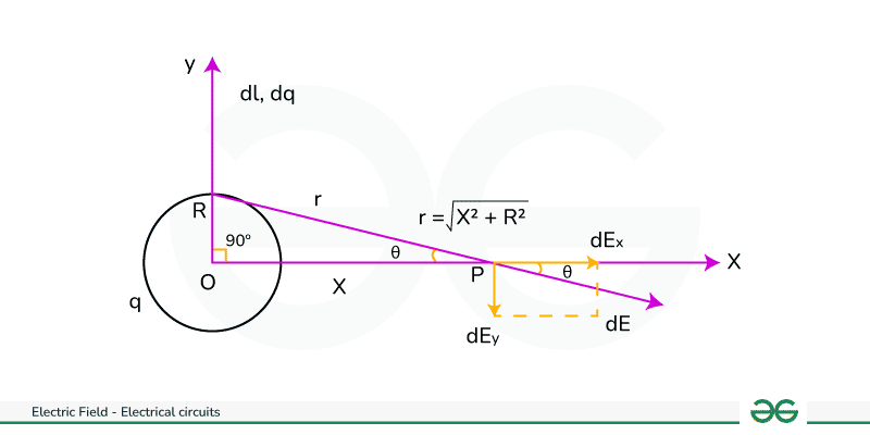
Let AB be the length of element dl.
The charge on the element AB is,
dq = (q × dl)/2πR
Electric field intensity at P due to charge element AB is,
|dE| = k dq/(CP)2
where, k = constant
|dE| = k dq/(R2 + x2)
Now, resolve the electric field intensity dE into two rectangular components, that is
dE sinθ along the y-axis and dE cosθ along the x-axis.
And for diametrically opposite elements of the charged ring, the perpendicular components of the electric field intensity will nullify each other, resulting in,
∫dE sinθ = 0.
Whereas components along the axis of the charged ring will undergo integration. That is, ∫dE cosθ.
Hence, the resultant electric field intensity E at P is | E | = ∫dE cosθ
In △OPC, cos θ = OP/CP = x/√(R2 + X2 ) and |dE| = k dq/(R2 + x2)
Therefore, |E| = ∫k × x × dq/(R2 + X2 )(√(R2 + X2 )
|E| = k × q × x/(R2 + X2 )3/2
The direction of E is along the positive x-axis of the loop.
Electric Field Due to a Uniformly Charged Sphere
Now, let us talk about the electric field due to a uniformly charged sphere.
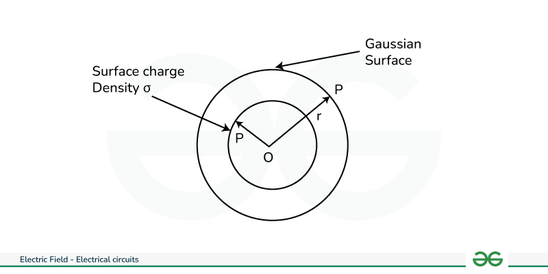
Electric Field Outside the Shell
To find out the electric field intensity at a point P outside the spherical shell when OP = r.
The Gaussian surface was taken as a sphere having radius r, while the electric field intensity will remain the same at every point seen on the Gaussian surface.
Thus, Gauss theorem becomes,
∮
or it can be also be given as,
E∮dS = q/ε0
E × (4πr2) = q/ε0
Therefore, the electric field become,
E =
From the above equation we can say that the electric field outside the shell is similar to the electric field due to a point charge. Thus outside the sphere, the electric field behaves as though it is due to a point charge (carrying all the charge of the shell) at the Centre of the shell.
Electric Field Inside the Shell
If the point P lies inside the spherical shell, then the Gaussian surface is a surface of a sphere having radius r. Since no charge is present inside the spherical shell, the Gaussian surface encloses no charge. Hence, q = 0.
To derive the value you can put the value of q = 0 in the formula E = q/ε0 which will give the result zero.
Electric Field at the Surface of the Shell
At the surface of the shell, r = R
E = q/(4πR2ε0)
If σ is the surface charge density then
q = (4πR2ε0).σ
Since, we have E = q/(4πR2ε0)
Putting value of q = (4πR2ε0).σ we get
E = σ/ε0
Applications of Electric Field
The applications of electric field are mentioned below:
- Electroporation: A technique in which electric fields are used to make pores in cell membranes to insert drugs, medicines, or genes. It is generally used in cloning processes.
- Electric fields play a role in studying tissue dynamics and controlling crystallization processes like nucleation and crystal growth, etc.
- Electric fields are used to impart kinetic energy to charged particles as they travel through the particle accelerator
- Electric fields are used to accelerate charged particles (ions) through a vacuum chamber, allowing scientists to separate ions based on their mass-to-charge ratios
- Electric fields cause polarization of dielectric materials, resulting in the accumulation of electric charge and increased capacitance.
Solved Examples on Electric Field
Example 1. A force of 100 N is acting on the charge 10 μ C at any point. Determine the electric field intensity at that point.
Solution:
Given:
Force F = 100 N
Charge q = 10 μ C
Electric field formula is given by
E = F / q
E = 100N / 10×10−6C
E = 107 N/C.
2. Calculate the electric field at points P, Q for the following two cases.(figure is provided below).
(a) For a charge of +1 µC placed at the origin.
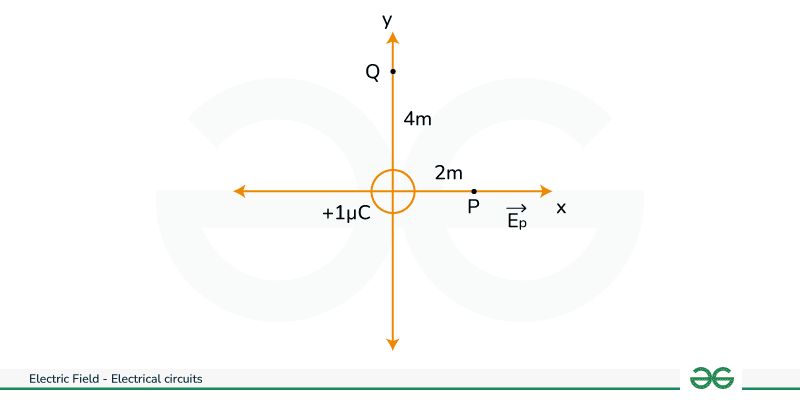
The magnitude of the electric field at point P is
Ep = {1/4πε }(q/r2 )
Ep = (9 × 109 × 1 × 10-6 )/4 = 2.25 × 10³ NC-1
Since, the source charges is positive, the electric field points away from the charge,
So the electric field at the point P is given by
For the point Q;
EQ = 9 × 109 × 1 × 10-6/16 = 0.56 × 10³ NC-1
(b)For a charge of -2 µC placed at the origin
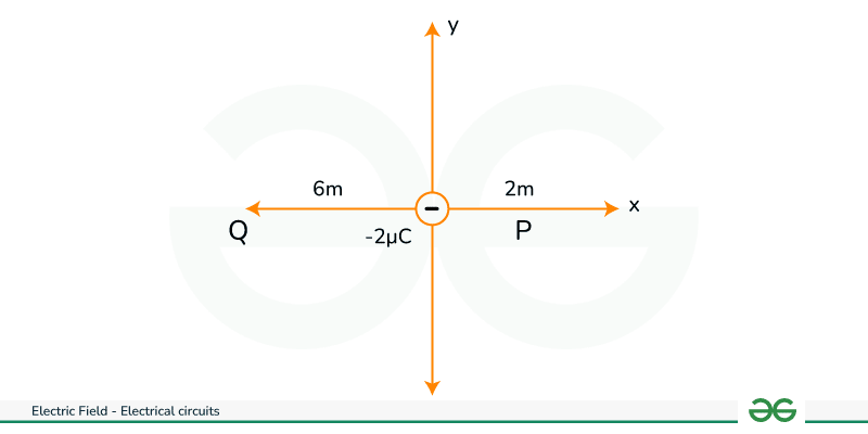
The magnitude of the electric field at point P is
Ep = {1/4πε }(q/r2 )
Ep = (9 × 109 × 2 × 10-6)/4
Ep = 4.5 × 10³ NC-1
Since, the charge is negative, the electric field points towards,
So, the electric field at point P is given by
For the point Q = (9 × 109 × 1 × 10-6 )/36 = 0.5 × 10³ NC-1
FAQs on Electric Field
What has an electric field?
An electric charge has an electric field
What is an Electric Field?
An electric field at a particular location indicates the force exerted on a unit positive test charge placed at that point.
What is electric field formula?
The electric field formula is given as E = F/q = {1/4πε0}(Q/r2 )
What is electric flux?
Electric flux represents the total number of electric field lines passing through a specified area per unit time.
What is a point charge?
A point charge refers to a theoretical charge situated at a point in space.
What is unit of electric field?
The unit of electric field in NC-1
What is k in electric field formula?
k is coulomb constant in electric field formula
Electric Field Lines
Electric field lines are a representation used to visualize the electric field surrounding charged objects. They provide a way to understand the direction and strength of the electric field at different points in space. It helps analyze electric fields in various situations, such as around point charges, between parallel plates, or within complex arrangements of charges.
In this article, we will learn in detail about electric field lines, their properties, and the rules to draw electric field lines for different charges.
What is Electric Field Line?
The concept of an electric field line is used to define an electric field near charged particles. They were first used by Michael Faraday to define an electric field due to an electron and a proton.
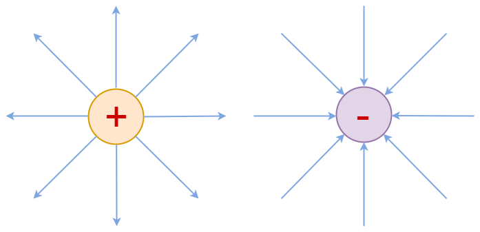
Electric field lines are imaginary lines that are used to visualize electric field around a charge in real life. They are also called electric lines of force. The tangent drawn at any point on electric field lines shows the direction of electric field at that particular point.
They are regular lines without any break and are curved in nature. They are curved in nature and not linearly straight. In case of the positive charge the direction of electric field lines is radially outwards and in case of negative charge the direction of electric field line is radially inwards. Also, the density of the electric field lines shows the strength of the electric field i.e. the more electric field lines in an area the more the strength of the electric field there.
Properties of Electric Field Lines
The electric field lines have the following properties:
- Electric field lines never intersect each other.
- Electric field lines are always perpendicular to the surface of the charge.
- For a single charge, the field lines go from the surface of the charge to up to infinity.
- The magnitude of the electric field and the number of field lines, both are proportional to each other.
- In a uniform electric field, field lines are evenly spaced and parallel to each other.
- In a non-uniform electric field, the field lines are closer together where the field is stronger and farther apart where it is weaker.
- Electric field lines originate from positive charges and terminate on negative charges.
Rules for Drawing Electric Field Lines
The rules used for drawing electric field lines are discussed below:
- For positive charge, electric field lines always start at their surface and go up to infinity, for negative charge it starts from infinity and ends at its surface.
- The more field lines in an area the more the strength of the electric field.
- Electric field lines never intersect each other.
- Electric field and electric field lines are always tangent at the point where they pass through.
Electric Field Lines for Different Charges
Using the above rules we can draw electric field lines for different configuration of electric charges
Electric Field Lines for Individual Charges
In case of individual positive charge, the direction of electric field line is radially outwards and in case of individual negative charge the direction of the electric field line is radially inwards.
Electric Field Lines for Two Equal and Unlike Charge
For two equal and unlike charge the electric field will originate from positive charge and enter into negative charge forming a close loop
Electric Field Lines for Two Equal and Like Charge
In case of two equal and like charge both will exert repulsive force on each other and the arrangement of electric field lines will be either side of each charge.
Related Articles
Solved Examples on Electric Field Lines
Example 1: At any time, a force of 10 N is operating on the charge of 18 μC. Determine the intensity of the electric field at that location.
Solution:
Given:
F = 10 N, q = 18 μCE = F/q
E = 10 / 18 × 10-6
E = 5.5 × 10⁵ N/C
Example 2: Calculate the strength of the electric field at a distance of 12 cm with a voltage of 68 V.
Solution:
Given:
V = 68 V, r = 12 cmE = V/r
E = 68/12
E = 5.66 V/cm
Example 3: A force of 12 N is acting on the charge of 27 μC. Find Electric Field.
Solution:
Given:
F = 12 N, q = 27 μCE = F/q
E = 12 / 27 × 10-6
E = 4.44 × 10⁵ N/C
Example 4: The electric field is 6.4 N/C at a distance of 6 cm then find the voltage.
Solution:
Given:
E = 6.4 N/C, r = 6 cmV = E × r
V = 6.4 × 6
V = 38.4 V
FAQs on Electric Field Lines
What electric field line are also called?
Electric field lines are also called as electric lines of force
What is electric field?
Electric field is the region around a charge in which it exerts a force on other charge
What is the SI unit of the Electric Field?
N/C (Newton/Coulomb) is the SI unit for an electric field.
State Coulomb’s law in Electrostatics.
Coulomb’s Law states that, “Magnitude of the electrostatic force of attraction or repulsion between any two point charges is directly proportional to the product of their magnitudes, and is inversely proportional to the square of the distance between them.”
What is an electric charge?
Electric Charge is the property of any particle by the virtue of which any particle experience forces in an electric and magnetic field.
What is the relation between electric field strength and density of lines?
Electric field strength is directly proportional to the density of electric field lines.
How is electric field strength related to distance?
Electric field lines follows inverse square rule with distance i.e. E ⋉ 1/r2
What is Electric Flux?
Electric flux is a fundamental concept in physics that helps us understand and quantify the electric field passing through a given surface. It provides a means to describe the flow of electric field lines through an area. Electric flux forms the basis of Gauss’s Law, to calculate the net charge enclosed inside a given Gaussian surface, which says that the flux through a surface will be the result of the total (or net) charge enclosed inside it.
In this article, we will learn about the basics of electric flux, its types, electric flux density, and electric flux through various types of surfaces.

Table of Content
What is Electric Flux?
Electric flux is the estimation of the total number of electric field lines (imaginary lines considered around a charged particle, these are thought to originate from the positive electric charges and thought to sink in negative electric charges), passing through a given closed surface, it can also be defined as the total charge contained in a closed surface (Gauss’s Law). It is a vector quantity and has direction. The electric flux is considered to have a sign associated with it which denotes whether the electric field lines are entering into the surface or coming out of the surface. Thus,
Definition of Electric Flux
Electric flux is the measure of electric lines of force (or electric field lines) passing through a given closed surface. It is a scalar quantity, representing the total number of electric field lines passing through a given surface.
Electric Flux Symbol
Electric flux is denoted by a Greek letter Φ, which is pronounced as phi i.e., Φ.
Electric Flux Formula
The electric flux depends on the different parameters namely, the strength of the electric lines of forces, the area of the surfaces and it also depends on the orientation between the surface area and the electric lines of forces. These quantities together yields electric fields through the surface and they are related as:
Φ = E • A
OR
Φ = E A cos θ
Where,
- Φ denotes the electric flux,
- E denotes the electric field strength,
- A denotes the area of the closed surface, and
- θ denotes the angle between the electric field lines and the area vector
Factors Affecting Electric Flux
Some of the factors affecting electric flux are:
- Electric Field Strength (E): Φ ∝ E, thus it increase with the increase in electric filed lines.
- Area of the Surface (A): Φ ∝ A, thus its magnitude increases with increase of the area.
- cos θ : It attains the maximum value of 1 for θ = 0, and minimum value as -1 for θ = 180.
To take a deep dive into the topic how electric flux through continuous charge distribution works and what are surface, refer the articles:
SI Unit of Electric Flux
The unit of electric flux can be derived from putting the units of different values in the formula for calculating electric flux.
Φ = E × A × cos θ
Therefore,
Unit of (Φ) = Unit of (E) × Unit of (A) × Unit of cos θ
OR Unit of (Φ) = (V/m) × (m2) × 1
OR Unit of (Φ) = V-m.
Thus, the SI unit of electric flux is V-m (Volt-meter).
Electric Flux Dimensional Formula
Since electric flux depends on the some parameters, therefore dimensional formula of electric flux can be derived by putting the dimensional formula of the quantities together in the formula of electric flux.
[Φ] = [E] • [A]
[Φ] = [MLT-3A-1] • [L2] = [ML3T-3A-1]
Therefore, dimensional formula of electric flux is [ML3T-3A-1].
Types of Electric Flux
Since the electric flux also depends on the angle between the field lines and the area vector, it can have a negative or positive value.
- Positive Electric Flux: When the electric field lines pass outward through a closed surface, the electric flux is considered positive. This occurs when the electric field lines are in the same direction as the outward-pointing normal vector to the surface.
- Negative Electric Flux: When the electric field lines pass inward through a closed surface, the electric flux is considered negative. This happens when the electric field lines are in the opposite direction to the outward-pointing normal vector to the surface.
Properties of Electric Flux
Electric flux has several key properties that helps in understanding and analyzing electric fields. Some of the significant properties of electric flux are mentioned below:
- Electric flux is a scalar quantity, it has only magnitude with no direction. It quantifies the total number of electric field lines passing through a given surface, irrespective of its direction.
- The electric flux through a surface is directly proportional to the strength of the electric field passing through the surface (E). A stronger electric field will result in higher electric flux through the surface.
- It also depend on the angle between the area vector and the field lines.
- Electric flux follows the principle of superposition, i.e the total flux through a surface, is the sum of the individual fluxes through different parts of the surface.
Electric Flux Through Different Surfaces
From the discussion so far, we have got to know the relation between flux (Φ), Field Strength (E), and net area in the direction of field (A cosθ) as Φ = E A cos θ. So it far clear that electric flux through the surfaces depends on the area of the surface. Also according to the Gauss law, the total flux passing through a closed surface, depends on the net enclosed charge,
Φ = qenclosed / ε0
Where qenclosed is the total charge enclosed in the surface.
Now, we will discuss the electric flux through closed and open surface, and look what they are:
- Flux through Closed Surfaces
- Flux through Open Surfaces
- Electric Flux Through Special Geometries
Let’s discuss these in detail.
Flux through Closed Surfaces
Any surface that completely encloses a three-dimensional region, is a closed surface, examples of closed surfaces include cubes, spheres, cylinders etc. Closed surfaces, according to Gauss’s Law, are critical in understanding the relationship between the total electric flux passing through a surface and the charge enclosed within it.
According to Gauss’s Law that the total electric flux through a closed surface is proportional to the total charge enclosed by that surface, divided by the permittivity of the medium. The symmetric nature of closed surfaces simplifies the calculation of electric flux, enabling straightforward application of Gauss’s Law.
Φ = qenclosed/ε
where,
- q is the total charged enclosed inside a closed surface, and
- ε is the permittivity of the medium.
Flux through Open Surfaces
Unlike the closed surfaces the open surface doesn’t have a closed boundary and thus doesn’t encloses a volume. The direct application of Gauss’s Law become difficult in case of open surfaces, and thus determining the flux through open surface require integration of dot product of the electric field and the surface area vector over the entire surface.
These calculations are more complex than that of the closed surfaces due to the lack of symmetry, and they involve integrating over irregularly shaped surfaces. Open surfaces includes planes, sheets, rings etc.
The flux Φ through an open surface can be determined using the integral calculation:
Φ = ∲ E ․ dA
Where
- E is the electric field,
- dA is the small area element from the surface, and
- The dot product of the electric field and the differential area vector is integrated over the entire open surface to calculate the total flux.
Electric Flux Through Special Geometries
Electric Flux thorough various special geometries are listed in the following table:
Geometry | Flux Expression | Explanation |
|---|---|---|
Cuboid | Φ = q0/ ε0 | where q0 is the total charge enclosed inside the cuboid and ε0 is the permittivity of the free space. |
One Face of Cuboid | Φ = q0/ 6ε0 | The flux will be equal in all the direction, hence 1/6 from each surface. |
Cylinder | Φ = q0/ ε0 | where q0 is the charge enclosed inside the cylinder, |
Cylinder Length placed in the field of strength E | Φ = 2 × π × r × l | where r is the radius of the base, L is the length of the cylinder. |
Sphere | Φ = q0/ε0 | when total enclosed charge is q0. |
Plain sheet placed in electric field of strength | Φ = E × A | This is an open surface, where A is its area and E is the field strength. |
Circular disc placed in electric field of strength | Φ = E × 2πr2 | where r is the radius of the disc placed in uniform field of strength E |
What is Electric Flux Density?
Electric field density is yet another important concept in electromagnetism, which is allows us to understand and predict how electric fields interact within substances, including insulators, conductors, and dielectrics. It signifies the amount of electric flux passing through a specific area within the material. It is also defined as the sum of the free charge effect (expressed through the electric field, E) and the impact of the material’s polarization (P) due to an external electric field. It is also referred to as electric displacement.
Electric field density is defined as, the electric flux passing through a unit area perpendicular to the direction of electric flux.
Electric Flux Density Formula
Electric flux is denoted by the symbol D. The formula for electric flux can be given as,
D = ε0E + P
Where,
- D is the electric flux density vector,
- ε0 is the permittivity of free space,
- E is the electric field strength and,
- P is the polarization vector, representing the dipole moment induced in the material per unit volume due to an external electric field.
SI Unit of Electric Flux Density
The SI unit of electric flux density can be derived from putting the units of different values in the formula of electric flux density.
D = ε0E + P
Putting,
- farads per meter (F/m) as unit of ε0
- volts per meter (V/m) as unit of E and,
- Polarization has a unit coulombs per square meter (C/m2).
The expression will yield the unit of Electric Flux density as C/m2.
The SI unit of electric flux density is coulombs per square meter (C/m²).
Electric Flux Density Dimensional Formula
The formula for Electric Flux Density can also be represented as,
D = Φ․A
Putting the dimensions of each quantities together we can get the dimensional formula of Electric Flux Density,
[D] = [Φ]․[A]
[D] = [ML3T-3A-1]/[L2]
Hence the dimensional formula of the Electric Flux Density Dimensional as [ML1T-3A-1].
Applications of Electric Flux
Electric flux is the basic behind various concepts in physics, including:
- Electric flux plays a key role in Gauss’s law, which relates the total electric flux through a closed surface and the total charge enclosed inside the surface.
- Electric flux is also used to understand the behavior of capacitors, which store electrical energy.
- Electric flux is used in the study of electromagnetic induction. When a magnetic field passing through a closed loop changes, it induces an electric field, and the concept of flux helps in understanding the induced electromotive force.
- Electric flux plays a crucial role in the study of dielectric materials.
Read More,
Solved Problems on Electric Flux
1. The surface of area 5 m² when an electric field of 2 N/C makes an angle of 180 degrees with the surface. What is the flux passing through the surface?
Given, A = 5 m2, E = 2 N/C and θ = 180
putting everything in the formula, Φ = E A cos θ
Φ = 2 × 5 × cos(180) = 10 × -1 = -10,
where negative sign indicates that the electric field lines are leaving the surface.
2. Derive the unit of electric flux.
Since,
Φ = E • A
Putting the unit of E as Volt per meter (V/m) and the unit of A as m2,
The unit of Φ = V/m × m2
Unit of Φ= V-m.
3. Derive the dimensional formula for electric flux.
We know the unit of Φ as V-m, putting the dimensions of the quantity in the formula the we get
Dimensional formula of electric flux = [MLT-3A-1] × [L2]
Dimensional formula of electric flux = [ML3T-3A-1].
Practice Problems on Electric Flux
Problem 1: Calculate the electric flux through a surface of area 1.414 m² when an electric field of 5 N/C makes an angle of 45 degrees with the surface.
Problem 2: A plane surface has an electric field of 100 N/C directed perpendicular to it. Calculate the electric flux through the surface if the area is 10 m².
Problem 3: Given a surface of area 5 m2 and the electric filed in the region as 10 N/C. The flux passing through the surface is 0. What is the angle between the area vector and electric field vector?
Problem 4: Can an object having a considerable area when placed in a considerable electric field having 0 electric flux passing through it? If yes explain.
Electric Flux: FAQs
1. Explain Electric Flux.
Electric flux is a measure of the total number of electric field lines passing through a given area. It is the measure of the strength of an electric field passing through a surface.
2. How to Calculate Electric Flux?
Electric flux (Φ) through a surface can be calculated as the dot product of the electric field (E) passing through the surface and the surface area (A) i.e.,
Φ = E • A = E A cos θ
3. What is the Unit of Electric Flux?
The SI unit of electric flux is the Volt-meter (V⋅m).
4. Define Electric Flux Density.
Electric Flux Density (D) is a measure of electric flux per unit area. It represents the electric field strength in a material, indicating how much electric flux passes through a given area.
5. What is the Dimensional Formula for Electric Flux?
The dimensional formula for electric flux is [ML3T-3A-1].
6. Can Electric Flux be Zero?
Yes, electric flux can be negative. It depends on the orientation of the surface with respect to the electric field.
7. What Does a Positive or Negative Sign in Electric Flux Indicate?
A positive electric flux indicates that the electric field is penetrating the surface in the direction of the normal to the surface, while a negative electric flux implies that the electric field is leaving the surface or penetrating in the opposite direction.
Continuous Charge Distribution
Electric charge is a fundamental feature of matter that regulates how elementary particles are impacted by an electric or magnetic field. Positive and negative electric charge exists in discrete natural units and cannot be manufactured or destroyed. There are two sorts of electric charges: positive and negative. When two items with an overabundance of one type of charge are relatively close to each other, they repel each other. When two things with excess opposing charges, one positively charged and the other negatively charged, are in close proximity, they attract each other.
Electric charge is a property shared by many fundamental, or subatomic, particles of matter. Electrons, for example, have a negative charge while protons have a positive charge. Neutrons, on the other hand, have no charge. Experiments have discovered that the negative charge of each electron has the same magnitude as the positive charge of each proton. A charge is measured in natural units, which are equivalent to the charge of an electron or proton, which is a fundamental physical constant.
Continuous Charge Distribution
Dealt with discrete charge combinations involves q1, q2,…, qn. The mathematical treatment is easier and does not require calculus, which is one of the reasons why we limited ourselves to discrete charges. However, working with discrete charges is impracticable for many reasons, and we must instead work with continuous charge distributions. All charges are tightly bonded together with very little space between them in continuous charge distribution.
Charges can be distributed in three ways, including
- Linear charge distribution.
- Surface charge distribution.
- Volume charge distribution.
Linear Charge Distribution
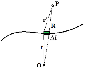
Linear Charge Distribution
When charges are dispersed equally along a length, such as around the circumference of a circle or along a straight wire, this is known as linear charge distribution. The linear charge distribution is symbolized by the symbol λ.
The linear charge density λ of a wire is defined by
where, ∆l is on the macroscopic scale, a small line element of wire, yet it contains a significant number of microscopic charged elements and ∆Q is the charge contained in that line element.

The units for λ are C/m.
Surface Charge Distribution
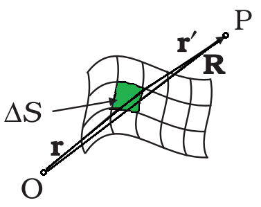
Surface Charge Distribution
It is impractical to characterize the charge distribution on the surface of a charged conductor in terms of the positions of the tiny charged elements. It is more practical to consider an area element S on the conductor’s surface (which is small on a macroscopic scale but large enough to contain numerous electrons) and specify the charge Q on that element.
A surface charge density σ at the area element by
The surface charge density σ is a continuous function.

The surface charge density as stated overlooks charge quantification and charge distribution discontinuities at the microscopic level, which is a smoothed out average of the microscopic charge density across an area element ∆S, which is huge microscopically but small macroscopically, reflects macroscopic surface charge density.
The unit of surface charge density σ is C/m2.
Volume Charge Distribution
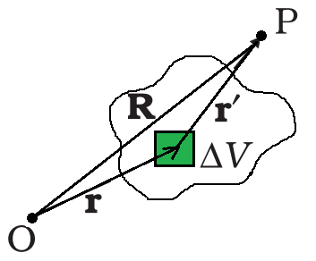
Volume Charge Distribution
Similarly, when a charge is spread uniformly over a volume then it is called volume charge distribution ρ, such as inside a sphere or a cylinder.
The volume charge density ρ (also known as charge density) is defined.
where ∆Q denotes the charge in the macroscopically small volume element ∆V, which contains a high number of microscopic charged constituents.

The unit of volume charge density ρ is C/m3.
Field due to a Continuous charge distribution
The field due to a continuous charge distribution may be calculated in the same manner as the field due to a system of discrete charges can be calculated. Assume that there is a charge density in continuous charge distribution in space. Take any suitable origin O and let r be the position vector of any point in the charge distribution. The charge density ρ may differ from point to point, i.e., it is a function of r. Divide the charge distribution into small volume elements of size ∆V. The charge in a volume element ∆V is ρ∆V.
Now, think any general point P inside or outside the distribution with position vector R. Electric field due to the charge ρ∆V is given by Coulomb’s law,

where r′ is the distance between the charge element and P, and  is a unit vector in the direction from the charge element to P.
The total electric field owing to the charge distribution is calculated using the superposition method that is by summing over electric fields due to different volume elements.

Sample Problems
Problem 1: What is linear charge distribution?
Solution:
When charges are dispersed equally along a length, such as around the circumference of a circle or along a straight wire, this is known as linear charge distribution. The linear charge distribution is symbolized by the symbol λ. The linear charge density λ of a wire is defined by
where, ∆l is on the macroscopic scale, a small line element of wire, yet it contains a significant number of microscopic charged elements and ∆Q is the charge contained in that line element. The units for λ are C/m.
Problem 2: A charge is distributed along an infinite curved line in space with linear charge distribution λ. What will be the amount of force on a point charge q kept at a certain distance from the line?
Solution:
Let the point charge is situated at a distance r from a small part dl on the line.
The charge stored in stat small part is λ.dl.
The force due to that small part will be directed towards the unit vector \hat{r}.
Therefore, force on that charge due to the entire linear charge distribution can be written as

Problem 3: A circular annulus of inner radius r and outer radius R has a uniform charge density a. What will be the total charge on the annulus?
Solution:
The total surface area of the annulus is π×(R2-r2)
It has an outer radius R and an inner radius r.
The surface charge density is the amount of charge stored on the unit surface area.
The surface charge density is a.
Therefore total charge on the annulus = π×a×(R2-r2).
Problem 4: A solid nonconducting sphere of radius 1m carries a total charge of 10 C which is uniformly distributed throughout the sphere. Determine the charge density of the sphere.
Solution:
The volume of the sphere = (4/3)πr3.
where r is the radius of the sphere.
Therefore, the charge density, ρ= total charge/[(4/3)πr3].
Now substituting the values,
ρ = 10/[(4/3)πr3]
ρ= 2.38 C/m3.
But if the sphere is conducting, we have to consider the surface charge density.
Problem 5: What is surface charge distribution?
Solution:
It is impractical to characterize the charge distribution on the surface of a charged conductor in terms of the positions of the tiny charged elements. It is more practical to consider an area element S on the conductor’s surface (which is small on a macroscopic scale but large enough to contain many electrons) and specify the charge Q on that element. A surface charge density σ at the area element by
The surface charge density σ is a continuous function. The surface charge density as stated overlooks charge quantification and charge distribution discontinuities at the microscopic level. , which is a smoothed out average of the microscopic charge density across an area element ∆S, which is huge microscopically but small macroscopically, reflects macroscopic surface charge density. The unit of surface charge density σ is C/m2.
Applications of Gauss’s Law
Gauss’s Law states that the total electric flux out of a closed surface equals the charge contained inside the surface divided by the absolute permittivity. The electric flux in an area is defined as the electric field multiplied by the surface area projected in a plane perpendicular to the field. Now that we’ve established what Gauss law is, let’s look at how it’s used. Application of Gauss Law is important for Class 12 students.
In this article, our main focus is on the Application of Gauss Law with a brief discussion of Gauss Law.
Table of Content
What is Gauss Law?
According to the Gauss law, the total flux linked with a closed surface is 1/ε0 times the charge enclosed by the closed surface.
Example: When a point charge q is placed inside a cube of edge ‘a’. Then, the flux through each face of the cube is q / 6ε0.
Applications of Gauss Law
We’ll look at a few of the applications of Gauss law in this article. To begin with, we know that in some situations, calculating the electric field is fairly difficult and requires a lot of integration. Gauss’s Law is used to make calculating the electric field easier.
Few applications of Gauss law involve finding:
- Electric field due to infinite straight wire.
- Electric field due to infinite plate sheet.
- Electric field due to thin spherical shell.
Electric Field due to Infinite Wire
Consider a wire that is infinitely long and has a linear charge density λ. To compute the electric field, we utilize a cylindrical Gaussian surface. The flux through the end of the surface will be 0 since the electric field E is radial. Because the electric field and the area vector are perpendicular to each other, this is the case. We may argue that the electric field’s magnitude will be constant since it is perpendicular to every point on the curved surface.

The curved cylindrical surface has a surface area of 2πrl. The electric flux flowing through the curve is equal to E × (2πrl).
According to Gauss’s Law:
ϕ = q ⁄ ε0
E × (2πrl) = λl ⁄ ε0
Hence, Electric Field due to Infinite Wire is given as
E = λ ⁄2πε0r
It’s important to note that if the linear charge density is positive, the electric field is radially outward. If the linear charge density is negative, however, it will be radially inward.
Electric Field due to Infinite Plane Sheet
Consider an infinite plane sheet with a cross-sectional area A and a surface charge density σ. The infinite plane sheet is in the following position:
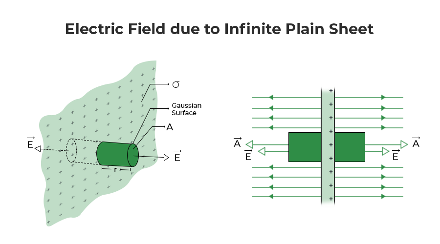
The electric field generated by an infinite charge sheet is perpendicular to the sheet’s plane. Consider a cylindrical Gaussian surface whose axis is perpendicular to the sheet’s plane. Gauss’s Law allows us to calculate the electric field E as follows:
ϕ = q ⁄ ε0
Charge q will be the charge density (σ) times the area (A) in continuous charge distribution. We shall only consider electric flow from the two ends of the imagined Gaussian surface when discussing net electric flux. We may explain it by the fact that the curved surface area and the electric field are perpendicular to each other, resulting in zero electric flux. As a result, the net electric flux:
ϕ = E A − (− E A)
ϕ = 2 E A
So,
2 E A = σ A ⁄ ε0
Hence, Electric Field Due to Infinite Plain Sheet is given as
E = σ ⁄ 2 ε0
The above formula shows that the electric field generated by an infinite plane sheet is independent of the cross-sectional area A.
Check: Electric charge formula
Electric Field due to Thin Spherical Shell
Consider a thin spherical shell with a radius “R”, charge q, and a surface charge density of σ (such that σ = q / 4 π r2). The shell possesses spherical symmetry. The electric field owing to the spherical shell can be calculated in two ways:
- Outside the spherical shell
- Inside the spherical shell
Electric Field Outside the Spherical Shell
Take a point P outside the spherical shell at a distance r from the center of the spherical shell to get the electric field. We use a Gaussian spherical surface with a radius of r and center ‘O’. Because all points are equally spaced “r” from the sphere’s center, the Gaussian surface will pass through P and experience a constant electric field E all around. So, Therefore, the total electric flux:
ϕ = q ⁄ ε0 = E × 4 π r2
Charge contained inside the surface, q = σ × 4 π R2
E × 4 π r2 = σ × 4 π R2 ⁄ ε0
E = σ R2 ⁄ ε0 r2
Electric field can also be written in the form of charge as (σ = q / 4 π r2)
Hence, Electric Field Outside Spherical shell is given as
E = k q ⁄r2
It’s important to keep in mind that if the surface charge density σ is negative, the electric field will be radially inward.
Electric Field Inside the Spherical Shell
Let’s look at point P inside the spherical shell to see how the electric field there is. We may use symmetry to create a spherical Gaussian surface that passes through P, is centered at O, and has a radius of r. Now, based on Gauss’s Law,
ϕ = q ⁄ ε0 = E × 4πr2
Since surface charge density is spread outside the surface, there is no charge contained inside the shell. Therefore, the electric field inside shell from the above formula is also zero, i.e.,
E = 0 (since q = 0)
Also, Check
Examples on Application of Gauss Law
Example 1: A hemispherical bowl of radius r is placed in a region of space with a uniform electric field E. Find out the electric flux through the bowl.
Solution:
The surface area of the given bowl, dA = 2 π r2
The field lines are parallel the axis of the plane of the bowl, i.e., θ = 0°
The electric flux, ϕ = E (dA) cosθ
= E (2 π r2) cos0°
= E (2 π r2)
Hence, the electric flux through the bowl is E (2 π r2).
Example 2: How does the electric flow via the Gaussian surface vary if the radius of the Gaussian surface containing a charge is halved?
Solution:
Even when the radius is half, the total charge contained by the Gaussian surface stays the same. As a result, according to Gauss’ theory, total electric flux remains constant. The electric flux will not vary as it passes through the Gaussian surface.
Example 3: A cylindrical surface of radius r and length l, encloses a thin straight infinitely long conduction wire with charge density whose axis coincides with the surface. Find the formula for the electric flux through the cylinder’s surface.
Solution:
A thin straight infinitely long wire has a uniform linear charge distribution. Consider the charge enclosed by the cylindrical surface be q.
Linear charge density, λ = q ⁄ l
Therefore, charge enclosed by the surface, q = λ l
The total electric flux through the surface of cylinder, ϕ = q ⁄ ε0
= λ l ⁄ ε0
Hence, the formula for electric flux through the cylinder’s surface is λ l ⁄ ε0.
Example 4: A charge of 2×10⁻⁸ C is distributed uniformly on the surface of a sphere of radius 2 cm. It is covered by a concentric, hollow conducting sphere of radius 5 cm. Find the electric field at a point 3 cm away from the center.
Solution:
Let us consider the below figure.
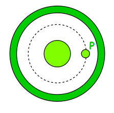
Sphere inside a concentric shell.
Assume we need to locate the field at point P. P should be used to draw a concentric spherical surface. All of the points on this surface are comparable, and the field at each of them will be equal in magnitude and radial in direction due to symmetry.
The flux through this surface = ∮ E dS
= E ∮ dS
= E (4 π r2)
where r = 3 cm = 3 × 10⁻² m
This flux is equal to the charge q contained within the surface divided by ε0 according to Gauss’ law.
Thus,
E (4 π r2) = q/ε0
E = q ⁄ 4 π ε0 r2
= ( 9 × 10⁹) × [(2 × 10⁻⁸)/(9 × 10-4)]
= 2 × 10⁵ N ⁄ C
The electric field at a point 3 cm away from the centre is 2 × 10⁵ N ⁄ C.
Application of Gauss Law FAQs
What is Gauss Law?
Gauss Law is one of the fundamental law of the electrostatics that states, “Total flux associated with a closed surface is 1/ε0 times the charge enclosed by the closed surface.”
What is the Application of Gauss law?
According to Gauss Law, the total electric flux coming out of a closed surface is equal to the charge enclosed inside the surface divided by the permittivity. Gauss Law is used to find the electric field of various objects.
What are Real-Life Applications of Gauss law?
Real-life applications of Gauss Law involve solving complex electrostatic problems with unique symmetries such as cylindrical, spherical, or planar symmetry.
What is a Gaussian Surface?
Gaussian surface is the surface of the on which the Gauss Law is applied. It is the 3-D surface that is used for finding electric field and explain various things.
Is Gauss Law Applicable to Non-Uniform Electric Field?
Yes, we can easily apply the Gauss law to non-uniform electric fields.
0 Comments